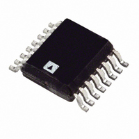
ADA4420-6ARQZ-RL Analog Devices Inc, ADA4420-6ARQZ-RL Datasheet - Page 10

ADA4420-6ARQZ-RL
Manufacturer Part Number
ADA4420-6ARQZ-RL
Description
Intrgratd VID Fltr & Buf For HD&SD Video
Manufacturer
Analog Devices Inc
Type
Video Filterr
Datasheet
1.ADA4420-6ARQZ.pdf
(12 pages)
Specifications of ADA4420-6ARQZ-RL
Applications
DVD, HD, Set-Top Boxes, Recorders
Mounting Type
Surface Mount
Package / Case
16-QSOP
Lead Free Status / RoHS Status
Lead free / RoHS Compliant
ADA4420-6
APPLICATIONS INFORMATION
OVERVIEW
With its high impedance inputs and high output drive, the
ADA4420-6 is ideally suited to video reconstruction and anti-
alias filtering applications. The high impedance inputs give
designers flexibility with regard to how the input signals are
terminated. Devices with DAC current source outputs that feed
the ADA4420-6 can be loaded in whatever resistance provides
the best performance, and devices with voltage outputs can be
optimally terminated as well. The ADA4420-6 outputs can each
drive up to two source-terminated, 75 Ω loads and, therefore, can
directly drive the outputs from set-top boxes and DVDs without
the need for a separate output buffer.
DISABLE
The ADA4420-6 includes a disable feature that can be used to
save power when a particular device is not in use. When disabled,
the ADA4420-6 typically draws only 7 μA from the supply. The
disable feature is asserted by pulling the DIS pin low.
Table 5 summarizes the operation of the disable feature.
Table 5. Disable Function
DIS Pin Connection
V
GND
INPUT AND OUTPUT COUPLING
Inputs to the ADA4420-6 can be ac- or dc-coupled. For dc-coupled
inputs, the signal must be completely contained within the input
range of 0 V to 2.1 V. When using ac-coupled inputs, the lowest
point of the signal is clamped to approximately 0 V. The ADA4420-6
outputs can be either ac- or dc-coupled.
When driving single ac-coupled loads in standard 75 Ω video
distribution systems, a minimum capacitance of 220 μF is
recommended to avoid line and field droop. There are two ac
coupling options when driving two loads from one output. One
option simply uses the same value capacitor on the second load,
while the other option uses a common coupling capacitor that
is at least twice the value used for the single load (see Figure 20
and Figure 21).
When driving two parallel 150 Ω loads (75 Ω effective load), the
3 dB bandwidth of the filters typically varies from that of the filters
with a single 150 Ω load (see Figure 4).
CC
or floating
Status
Disabled
Enabled
Rev. 0 | Page 10 of 12
PRINTED CIRCUIT BOARD (PCB) LAYOUT
As with all high speed applications, attention to the PCB layout
is of paramount importance. When designing with the ADA4420-6,
adhere to standard high speed layout practices. A solid ground
plane is recommended, and surface-mount, ceramic power supply
decoupling capacitors should be placed as close as possible to the
supply pins. Connect all of the ADA4420-6 GND pins to the
ground plane with traces that are as short as possible. Controlled
impedance traces of the shortest length possible should be used
to connect to the signal I/O pins and should not pass over any
voids in the ground plane. A 75 Ω impedance level is typically
used in video applications. When driving transmission lines,
include series termination resistors on the signal outputs of the
ADA4420-6.
When the ADA4420-6 receives its inputs from a device with
current outputs, the required load resistor value for the output
current is often different from the characteristic impedance of
the signal traces. In this case, if the interconnections are short
(<< 0.1 wavelength), the trace does not have to be terminated in
its characteristic impedance. Traces of 75 Ω can be used in this
instance, provided their lengths are an inch or two at most. This
is easily achieved because the ADA4420-6 and the device feeding it
are usually adjacent to each other, and connections can be made
that are less than one inch in length.
VIDEO ENCODER RECONSTRUCTION FILTER
The ADA4420-6 is easily applied as a reconstruction filter at the
DAC outputs of a video encoder. Figure 22 illustrates how to use
the ADA4420-6 in this type of application following an ADV734x
series video encoder, with a single-supply and ac-coupled outputs.
Figure 21. Driving Two AC-Coupled Loads with One Common Coupling Capacitor
Figure 20. Driving Two AC-Coupled Loads with Two Coupling Capacitors
ADA4420-6
ADA4420-6
470µF
75Ω
75Ω
75Ω
75Ω
220µF
220µF
CABLE
CABLE
75Ω
75Ω
CABLE
CABLE
75Ω
75Ω
75Ω
75Ω
75Ω
75Ω


