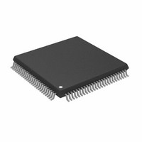
AD9882KSTZ-140 Analog Devices Inc, AD9882KSTZ-140 Datasheet - Page 32

AD9882KSTZ-140
Manufacturer Part Number
AD9882KSTZ-140
Description
IC,TV/VIDEO CIRCUIT,Video Digitizer,CMOS,QFP,100PIN,PLASTIC
Manufacturer
Analog Devices Inc
Datasheet
1.AD9882KSTZ-100.pdf
(40 pages)
Specifications of AD9882KSTZ-140
Applications
Video
Interface
Analog, DVI
Voltage - Supply
3.15 V ~ 3.45 V
Package / Case
100-LQFP
Mounting Type
Surface Mount
Lead Free Status / RoHS Status
Lead free / RoHS Compliant
Available stocks
Company
Part Number
Manufacturer
Quantity
Price
Company:
Part Number:
AD9882KSTZ-140
Manufacturer:
ADI
Quantity:
717
Company:
Part Number:
AD9882KSTZ-140
Manufacturer:
Analog Devices Inc
Quantity:
10 000
AD9882A
Table 45. Active Hsync Results
Hsync Detect
Register
0x15,Bit 7
0
0
1
1
X
AHS = 0 means use the Hsync pin input for Hsync. AHS = 1
means use the SOG pin input for Hsync. The override bit is in
Register 0x10, Bit 4.
0x16 6
This bit reports the status of the Hsync input polarity detection
circuit. It can be used to determine the polarity of the Hsync
input. The detection circuit’s location is shown Figure 20.
Table 46. Detected Hsync Input Polarity Status
Hsync Polarity Status
0
1
0x16 5
This bit indicates which Vsync source is being used for the
analog interface, the Vsync input or output from the sync
separator. If the override bit (0x10, Bit 1) is set to Logic 1, then
this bit will be forced to the same state as Bit 0 in Register 0x10.
Table 47. Active Vsync Results
Vsync Detect
Register
0x16 Bit 5
0
1
X
AVS = 0 means Vsync input. AVS = 1 means sync separator.
The override bit is in Register 0x10, Bit 1.
0x16 4
This bit reports the status of the Vsync output polarity
detection circuit. It can be used to determine the polarity of the
Vsync output. The detection circuit’s location is shown in
Figure 20.
Table 48. Detected Vsync Input Polarity Status
Vsync Polarity Status
0
1
Detected Hsync Input Polarity Status
AVS Active Vsync
Detected Vsync Output Polarity Status
SOG Detect
Register
0x,10 Bit 4
0
1
0
1
X
Override
Register
0x10 Bit 1
0
0
1
Result
Hsync polarity is negative/active low.
Hsync polarity is positive/active high.
Result
Vsync polarity is active high.
Vsync polarity is active low.
1
Override
Register
0x,15 Bit 6
0
0
0
0
AVS
0
1
Bit 0 in 0x10
AHS
Register
0x16,Bit 7
Bit 3 in
0x10
1
0
Bit 3 in
0x10
Bit 3 in
0x10
Rev. 0 | Page 32 of 40
0x16 3 Detected Coast Polarity Status
This bit reports the status of the coast input polarity detection
circuit. The detection circuit’s location is shown in Figure 20.
This bit applies only to the internal coast and does not apply
when coast is disabled.
Table 49. Detected Coast Input Polarity Status
Hsync Polarity Status
0
1
0x16 2
This bit reports wherever HDCP keys are detected.
Table 50. Key Read Verification
Detect
0
1
0x1B 7
The MDA and MCL three-state feature allows the EEPROM to
be programmed in-circuit. The MDA/MCL port must be three-
stated before attempting to program the EEPROM using an
external master. The keys are stored in an I
serial EEPROM of at least 512 bytes. The EEPROM should have
a device address of 0xA0.
0x1C 0 RxC Connect
The RxC (DVI differential clock pair) can be disconnected via
software if the HDCP specified hot plug detect does not work to
resynchronize the HDCP transmitter engine. To use this
function, write this bit to 0 (0xR1C to 0x0E) then back to 1
(0xR1C to 0x0F). This signals to the DVI transmitter to restart
the HDCP protocol. It is recommended that the user perform
this toggle of the bit whenever switching from analog to digital
inputs.
Table 51. DVI Clock Connect
Set
0
1
2-WIRE SERIAL CONTROL PORT
A 2-wire serial control interface is provided. Two AD9882A
devices can be connected to the 2-wire serial interface, with
each device having a unique address.
The 2-wire serial interface comprises a clock (SCL) and a
bidirectional data (SDA) pin. The analog flat panel interface
acts as a slave for receiving and transmitting data over the serial
interface. When the serial interface is not active, the logic levels
on SCL and SDA are pulled high by external pull-up resistors.
Data received or transmitted on the SDA line must be stable for
the duration of the positive-going SCL pulse. Data on SDA must
Key Read Verification
MDA and MCL Three-State
Function
Not detected
Detected
Function
RxC lines disconnected (open).
RxC lines connected internally.
Result
Coast polarity is negative/active low.
Coast polarity is positive/active high.
2
C compatible 3.3 V


