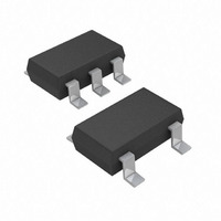
AD8613AUJZ-REEL7 Analog Devices Inc, AD8613AUJZ-REEL7 Datasheet

AD8613AUJZ-REEL7
Specifications of AD8613AUJZ-REEL7
Available stocks
Related parts for AD8613AUJZ-REEL7
AD8613AUJZ-REEL7 Summary of contents
Page 1
FEATURES Offset voltage: 2.2 mV maximum Low input bias current maximum Single-supply operation: 1 Low noise: 22 nV/√Hz Micropower: 50 μA/amplifier maximum over temperature No phase reversal Unity gain stable Qualified for automotive applications ...
Page 2
AD8613/AD8617/AD8619 TABLE OF CONTENTS Features .............................................................................................. 1 Applications ....................................................................................... 1 General Description ......................................................................... 1 Pin Configurations ........................................................................... 1 Revision History ............................................................................... 2 Specifications ..................................................................................... 3 Absolute Maximum Ratings ............................................................ 5 REVISION HISTORY 3/10—Rev Rev. E Changes to General ...
Page 3
SPECIFICATIONS Electrical characteristics Table 1. Parameter INPUT CHARACTERISTICS Offset Voltage Offset Voltage Drift AD8613 Input Bias Current Input Offset Current Input Voltage Range Common-Mode Rejection Ratio Large Signal Voltage Gain Input Capacitance OUTPUT ...
Page 4
AD8613/AD8617/AD8619 Electrical characteristics 1 Table 2. Parameter INPUT CHARACTERISTICS Offset Voltage Offset Voltage Drift AD8613 Input Bias Current Input Offset Current Input Voltage Range Common-Mode Rejection Ratio Large Signal Voltage Gain Input Capacitance OUTPUT ...
Page 5
ABSOLUTE MAXIMUM RATINGS T = 25°C, unless otherwise noted. A Table 3. Parameter Supply Voltage Input Voltage Input Current Differential Input Voltage Output Short-Circuit Duration to GND Storage Temperature Range Lead Temperature (Soldering, 60 sec) Operating Temperature Range Junction Temperature ...
Page 6
AD8613/AD8617/AD8619 TYPICAL PERFORMANCE CHARACTERISTICS ±2.5 V, unless otherwise noted. SY 1800 V = 5.5V SY –0.5V < V < +5.5V CM 1600 T = 25°C A 1400 1200 1000 800 600 400 200 0 INPUT ...
Page 7
25ºC A 100 V – SOURCE 10 1 SINK V OL 0.1 0.01 0.001 0.01 0.1 1 LOAD CURRENT (mA) Figure 12. Output Voltage to Supply Rail vs. Load Current ...
Page 8
AD8613/AD8617/AD8619 100 V 100 100 1k 10k FREQUENCY (Hz) Figure 18. Output Impedance vs. Frequency 25° ...
Page 9
OUT V = ±2. 10kΩ p-p IN TIME (20ms/DIV) Figure 24. No Phase Reversal AND 2.7V SY TIME (1s/DIV) Figure 25. 0.1 Hz ...
Page 10
AD8613/AD8617/AD8619 ±0.9 V, unless otherwise noted. SY 450 < V < 1.8V 400 25°C A 350 300 250 200 150 100 50 0 INPUT OFFSET VOLTAGE (µV) ...
Page 11
25° – 100 LOAD CAPACITANCE (pF) Figure 34. Small Signal Overshoot vs. Load Capacitance 10kΩ L ...
Page 12
AD8613/AD8617/AD8619 OUTLINE DIMENSIONS 3.20 3.00 2.80 5. 3.20 4.90 3.00 4.65 1 2.80 4 PIN 1 IDENTIFIER 0.65 BSC 0.95 0.85 1.10 MAX 0.75 0.15 6° 0.40 0.05 0° 0.25 COPLANARITY 0.10 COMPLIANT TO JEDEC STANDARDS MO-187-AA Figure ...
Page 13
BSC 4. PIN 1 0.65 BSC 1.05 1.20 1.00 MAX 0.80 0.15 SEATING 0.05 0.30 PLANE COPLANARITY 0.19 0.10 COMPLIANT TO JEDEC STANDARDS MO-153-AB-1 Figure 41. 14-Lead Thin Shrink Small ...
Page 14
AD8613/AD8617/AD8619 1.60 BSC * 0.90 MAX 0.70 MIN 0.10 MAX PIN 1 INDICATOR 0.90 MAX 0.85 NOM SEATING PLANE 2.90 BSC 5 4 2.80 BSC 0.95 BSC 1.90 BSC * 1.00 MAX 0.20 0.08 0.50 SEATING PLANE ...
Page 15
... AD8613AKSZ-REEL −40°C to +125°C AD8613AKSZ-REEL7 −40°C to +125°C AD8613AUJZ-R2 −40°C to +125°C AD8613AUJZ-REEL −40°C to +125°C AD8613AUJZ-REEL7 −40°C to +125°C AD8617ACPZ-R2 −40°C to +125°C AD8617ACPZ-R7 −40°C to +125°C AD8617ACPZ-RL −40°C to +125°C AD8617ARMZ − ...
Page 16
AD8613/AD8617/AD8619 NOTES ©2005–2010 Analog Devices, Inc. All rights reserved. Trademarks and registered trademarks are the property of their respective owners. D05622-0-3/10(E) Rev Page ...


