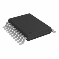
AD7998BRU-1 Analog Devices Inc, AD7998BRU-1 Datasheet - Page 7

AD7998BRU-1
Manufacturer Part Number
AD7998BRU-1
Description
IC,Data Acquisition System,8-CHANNEL,12-BIT,TSSOP,20PIN,PLASTIC
Manufacturer
Analog Devices Inc
Datasheet
1.AD7997BRUZ-1.pdf
(32 pages)
Specifications of AD7998BRU-1
Number Of Bits
12
Sampling Rate (per Second)
188k
Data Interface
I²C, Serial
Number Of Converters
1
Power Dissipation (max)
2.2mW
Voltage Supply Source
Single Supply
Operating Temperature
-40°C ~ 85°C
Mounting Type
Surface Mount
Package / Case
20-TSSOP (0.173", 4.40mm Width)
Lead Free Status / RoHS Status
Contains lead / RoHS non-compliant
For Use With
EVAL-AD7998CBZ - BOARD EVALUATION FOR AD7998CBZ
Lead Free Status / RoHS Status
Contains lead / RoHS non-compliant
I
Guaranteed by initial characterization. All values measured with input filtering enabled. C
t
High speed mode timing specifications apply to the AD7997-1/AD7998-1 only. Standard and fast mode timing specifications apply to
both the AD7997-0/AD7998-0 and the AD7997-1/AD7998-1. See Figure 2. Unless otherwise noted, V
T
Table 3.
Parameter
f
t
t
t
t
t
t
t
t
t
f
SCL
1
2
3
4
5
6
7
8
9
2
A
1
measured between 0.3 VDD and 0.7 VDD.
C TIMING SPECIFICATIONS
=T
MIN
to T
MAX
Conditions
Standard mode
Fast mode
High speed mode
Standard mode
Fast mode
High speed mode
Standard mode
Fast mode
High speed mode
Standard mode
Fast mode
High speed mode
Standard mode
Fast mode
High speed mode
Standard mode
Fast mode
High speed mode
Standard mode
Fast mode
High speed mode
Standard mode
Fast mode
Standard mode
Fast mode
High speed mode
Standard mode
Fast mode
High speed mode
C
C
C
C
C
C
C
C
C
C
.
B
B
B
B
B
B
B
B
B
B
= 100 pF max
= 400 pF max
= 100 pF max
= 400 pF max
= 100 pF max
= 400 pF max
= 100 pF max
= 400 pF max
= 100 pF max
= 400 pF max
Min
4
0.6
60
120
4.7
1.3
160
320
100
10
0
0
4.7
0.6
160
4
0.6
160
4.7
1.3
4
0.6
160
10
20
250
0
0
20 + 0.1 C
AD7997/AD7998 Limit at T
B
Max
100
400
3.4
1.7
3.45
0.9
70
150
1000
300
80
160
2
Rev. 0 | Page 7 of 32
Unit
kHz
kHz
MHz
MHz
µs
µs
ns
ns
µs
µs
ns
ns
ns
ns
ns
µs
µs
ns
ns
µs
µs
ns
µs
µs
ns
µs
µs
µs
µs
ns
ns
ns
ns
ns
MIN
, T
MAX
Description
Serial clock frequency
t
t
t
t
t
t
t
t
t
HIGH
LOW
SU;DAT
HD;DAT
SU;STA
HD;STA
BUF
SU;STO
RDA
, bus free time between a stop and a start condition
, rise time of SDA signal
, SCL low time
, SCL high time
, setup time for a repeated start condition
, setup time for stop condition
B
, data setup time
, hold time (repeated) start condition
, data hold time
refers to capacitive load on the bus line. t
DD
= 2.7 V to 5.5 V; REF
AD7997/AD7998
IN
= 2.5 V;
r
and


