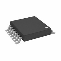
AD5260BRUZ20-RL7 Analog Devices Inc, AD5260BRUZ20-RL7 Datasheet - Page 22

AD5260BRUZ20-RL7
Manufacturer Part Number
AD5260BRUZ20-RL7
Description
IC,Digital Potentiometer,TSSOP,14PIN,PLASTIC
Manufacturer
Analog Devices Inc
Datasheet
1.AD5260BRUZ200.pdf
(24 pages)
Specifications of AD5260BRUZ20-RL7
Taps
256
Resistance (ohms)
20K
Number Of Circuits
1
Temperature Coefficient
35 ppm/°C Typical
Memory Type
Volatile
Interface
4-Wire SPI Serial
Voltage - Supply
4.5 V ~ 16.5 V, ±4.5 V ~ 5.5 V
Operating Temperature
-40°C ~ 85°C
Mounting Type
Surface Mount
Package / Case
14-TSSOP
Resistance In Ohms
20K
Lead Free Status / RoHS Status
Lead free / RoHS Compliant
Available stocks
Company
Part Number
Manufacturer
Quantity
Price
AD5260/AD5262
ate state occurs that may not be acceptable for certain applications.
As a result, different devices can also be used in daisy-chaine
mode so that par
simultaneously.
RESISTANCE SCALING
The AD5260/AD5262 offer 20 kΩ, 50 kΩ, and 200 kΩ nominal
resistance. For users who need lower resistance and still main-
tain the numbers of step adjustment, they can place multip
devices in parallel. For example, Figure 68 shows a simple
scheme of paralleling both channels of the AD5262. To adjust
half of the resistance linearly per step, users need t
both channels coherently with the same settings.
Figure
68. Reduce Resistance by Half with Linear Adjustment Characteristics
Figure 67. Programmable Os
R1 = R1' = R2B = AD5262
D1 = D2 = 1N4148
2.2nF
ADJUSTMENT
C
FREQUENCY
ts can be programmed to the same setting
10kΩ
R
AD5262
B
A
LD
A1
B1
W
1kΩ
VN
R1
V
DD
W1
VP
cillator with Amplitude Control
B
A2
B2
W
10kΩ
OP1177
R2B
2.2nF
+5V
–5V
C'
A
W2
2.1kΩ D1
R2A
AMPLITUDE
ADJUSTMENT
A
10kΩ
W
U1
R'
B
D2
o program
V
O
le
Rev. A | Page 22 of 24
d
In voltage divider mode, a much lower resistance can be achieved
by paralleling a discrete resistor as shown in Figure 69. The
equivalent resistance becomes
Figure 68 and Figure 69 show that the digital potentiometers
change steps linearly. However, log taper adjustment is usually
preferred in applications like audio control. Figure 70 shows
another method of resistance scaling. In this circuit, the smaller
R2 is with respect to R
characteristic behaves.
R
R
Figure 70. Resistor Scaling with Log Adjustment Characteristics
WB
WA
_
_
eq
eq
=
=
Figure 69. Lowering the Nominal Resistance
⎛ −
⎜
⎝
256
1
D
256
(
R1
D
R1
R2
A
B
AB
V
//
⎞
⎟
⎠
i
(
, the more the pseudo-log taper
R2
R1
W
R2 << R1
)
//
+
R2
R2
R1
R
W
)
A
B
+
R
W
W
V
O
(16)
(17)


