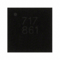
A8500EECTR-T Allegro Microsystems Inc, A8500EECTR-T Datasheet - Page 9

A8500EECTR-T
Manufacturer Part Number
A8500EECTR-T
Description
IC,Laser Diode/LED Driver,LLCC,28PIN,PLASTIC
Manufacturer
Allegro Microsystems Inc
Type
Backlight, White LED, RGBr
Datasheet
1.A8500EECTR-T.pdf
(16 pages)
Specifications of A8500EECTR-T
Topology
PWM, Step-Up (Boost)
Number Of Outputs
8
Internal Driver
Yes
Type - Primary
Backlight
Type - Secondary
RGB, White LED
Frequency
2MHz
Voltage - Supply
4.2 V ~ 5.5 V
Voltage - Output
28V
Mounting Type
Surface Mount
Package / Case
26-WFQFN Exposed Pad
Operating Temperature
-40°C ~ 85°C
Current - Output / Channel
25mA
Internal Switch(s)
Yes
Lead Free Status / RoHS Status
Lead free / RoHS Compliant
Efficiency
-
Lead Free Status / RoHS Status
Lead free / RoHS Compliant
Other names
620-1204-2
A8500
This current is multiplied internally with a gain of 210, and then
mirrored on all enabled LEDx pins. This sets the maximum cur-
rent through the LEDs, referred to as “100% current.” The effects
of the value of R
The LED current can be reduced from 100% by any of three
alternative methods. These modes are:
•
•
•
Note: Only one dimming technique can be used at a time.
Serial Dimming Through the EN Pin.
high with PWM, and the APWM pin is low, the A8500 starts
up in serial programming mode. In this mode, series of pulses
applied to the EN pin are used to adjust the output current level,
I
listed in table 2.
As shown in the timing diagram in figure 4, serial dimming is
disabled during startup, for the t
Figure 4. Timing diagram for serial dimming.
LEDx
Table 2. Serial Dimming Levels
*The counter resets on the sixteenth pulse.
serial dimming through the EN pin,
on/off control (PWM) with an external PWM signal on the
PWM pin, and
analog dimming with an external PWM signal on the APWM pin
Pulses 0
EN
Pulse Count
I
LEDX
, to a proportion of the ISET current, in equal increments, as
0
1
2
3
4
5
6
7
ISET
100%×15/16
100%×14/16
100%×13/16
100%×12/16
100%×11/16
100%×10/16
100%× 9/16
t
HI(init)
are shown in figure 3.
100%
I
LEDx
t
LO
Shutdown
HI(init)
Pulse Count
1
100% ×1/16 level
100% as set by R
period. After that, the
When the EN pin is pulled
16*
10
12
13
14
15
11
8
9
2
3
100%×8/16
100%×7/16
100%×6/16
100%×5/16
100%×4/16
100%×3/16
100%×2/16
100%×1/16
ISET
100%
4
I
LEDx
t
HID
Dimming
Counter
Reset
.
Flexible WLED/RGB Backlight Driver
A8500 begins evaluating pulse patterns applied on the EN pin.
Until a valid series is evaluated, the count remains 0 and the
default I
range 1 to 15 is evaluated proportionately; for example, when
a series of 12 pulses is evaluated, I
4/16) of 100% current
continues to count if additional pulses are applied.
Figure 3. Effect of value of RISET on (A) “100% current” level, and
(B) LEDx gain.
25
20
15
10
212
210
209
208
207
206
205
204
203
202
211
1
5
0
t
0
HI
0
LEDx
75%
2
10
level remains at “100% current.” A count in the
10
3
t
HID
. At a 16th pulse, the counter resets to 0 and
20
20
(A)
(B)
for Medium Size LCDs
Dimming
Counter
Reset
115 Northeast Cutoff, Box 15036
Allegro MicroSystems, Inc.
Worcester, Massachusetts 01615-0036 (508) 853-5000
www.allegromicro.com
30
30
R
R
ISET
ISET
LEDx
(kΩ)
(kΩ)
40
40
81.2%
is set to 25% (100%
t
SHDN
50
50
V
IN
4.5
5.0
5.5
60
60
(V)
Dimming
Counter
Reset
70
×
70
9


