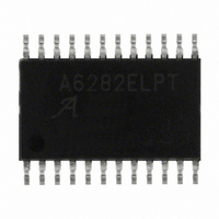
A6282ELPTR-T Allegro Microsystems Inc, A6282ELPTR-T Datasheet - Page 9

A6282ELPTR-T
Manufacturer Part Number
A6282ELPTR-T
Description
IC,Laser Diode/LED Driver,CMOS,TSSOP,24PIN,PLASTIC
Manufacturer
Allegro Microsystems Inc
Type
Linear (Non-Switching)r
Datasheet
1.A6282ELPTR-T.pdf
(13 pages)
Specifications of A6282ELPTR-T
Constant Current
Yes
Number Of Outputs
16
Internal Driver
Yes
Type - Primary
Backlight
Type - Secondary
Color, White LED
Frequency
30MHz
Voltage - Supply
3 V ~ 5.5 V
Voltage - Output
12V
Mounting Type
Surface Mount
Package / Case
24-TSSOP Exposed Pad, 24-eTSSOP, 24-HTSSOP
Operating Temperature
-40°C ~ 85°C
Current - Output / Channel
50mA
Internal Switch(s)
Yes
Lead Free Status / RoHS Status
Lead free / RoHS Compliant
Efficiency
-
Topology
-
Lead Free Status / RoHS Status
Lead free / RoHS Compliant
Other names
620-1268-2
A6282ELPTR-T
A6282ELPTR-T
Available stocks
Company
Part Number
Manufacturer
Quantity
Price
Company:
Part Number:
A6282ELPTR-T
Manufacturer:
TDK
Quantity:
24 000
A6282
Normal Operation
Serial data present at the SDI (Serial Data In) input is transferred
to the shift register on the transition from logic 0 to logic 1 of the
CLK (Clock) input pulse. On succeeding CLK pulses, the register
shifts data towards the SDO (Serial Data Out) output. The serial
data must appear at the input prior to the rising edge of the CLK
waveform.
Data present in any register is transferred to the respective latch
when the LE (Latch Enable) input is high (serial-to-parallel con-
version). The latches continue to accept new data as long as LE is
held high (level triggered).
Applications where the latches are bypassed (LE tied high)
require that the ¯ O ¯ ¯ ¯ E ¯ (Output Enable) input be high during serial
data entry. When ¯ O ¯ ¯ ¯ E ¯ is high, the output sink drivers are disabled
(off). The data stored in the latches is not affected by the state
of ¯ O ¯ ¯ ¯ E ¯ . With ¯ O ¯ ¯ ¯ E ¯ active (low), the outputs are controlled by the
state of their respective latches.
Setting Maximum Channel Current
The maximum output current per channel is set by a single exter-
nal resistor, REXT, which is placed between the REXT pin and
GND. The voltage on REXT, V
and is 1.21 V, typical.
EXT
, is set by an internal band gap
Functional Description
16-Channel Constant-Current LED Driver
The maximum channel output current can be calculated as:
where R
which should not be less than 374 Ω.
A chart of the maximum per channel (OUT0 to OUT15) constant
output current, I
the Operating Characteristics section.
Undervoltage Lockout
The A6282 includes an internal undervoltage lockout (UVLO)
circuit that disables the outputs in the event that the logic supply
voltage drops below a minimum acceptable level. This feature
prevents the display of erroneous information, a necessary func-
tion for some critical applications. Upon recovery of the logic
supply voltage after a UVLO event, all internal shift registers and
latches are set to 0. The A6282 is then in normal mode.
Thermal Shutdown Protection
If the junction temperature exceeds the threshold temperature,
T
tion temperature cools down through the thermal shutdown hys-
teresis, 15°C typical. The shift register and output latches register
will remain active during a thermal shutdown event. Therefore,
there is no need to reset the data in the output latches.
JTSD
I
or
I
O
O
(max) = (18483.1/ R
(max) = (18841.2/ R
, 165°C typical, the outputs will be turned off until the junc-
EXT
is the value of the user-selected external resistor,
O
(max), at various values of R
EXT
EXT
115 Northeast Cutoff
1.508.853.5000; www.allegromicro.com
Allegro MicroSystems, Inc.
Worcester, Massachusetts 01615-0036 U.S.A.
) + 0.67 , for V
) + 0.68 , for V
DD
DD
EXT
= 3.0 to 3.6 V ,
= 4.5 to 5.5 V ,
,
is shown in
9


