P11A1C0BJSZ00103MA Vishay, P11A1C0BJSZ00103MA Datasheet - Page 13
P11A1C0BJSZ00103MA
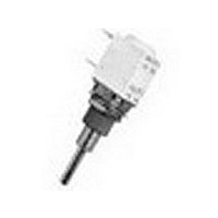
Manufacturer Part Number
P11A1C0BJSZ00103MA
Description
TRIMMERS & POTENTIOMETERS SFERNICE / P11A 1 C 0 BJ S Z00 10K 20% A E3
Manufacturer
Vishay
Type
Potentiometerr
Series
P11r
Specifications of P11A1C0BJSZ00103MA
Resistance
10kohm
Power Rating
1/2W
Tolerance (+ Or -)
20%
Number Of Turns
1Turn
Technology
Cermet
Mounting Style
Panel
Termination Style
Pin
Operating Temp Range
-55C to 125C
Failure Rate
Not Required
Shaft Diameter (mm)
3.17mm
Product Diameter (mm)
Not Requiredmm
Product Height (mm)
13.1mm
Product Depth (mm)
12.5mm
Temperature Coefficient
±500
Tolerance
20 %
Taper
Linear
Element Type
Conductive Plastic
Shaft Type
Slotted
Shaft Length
7/8 in
Shaft Diameter
1/8 in
Operating Temperature Range
- 55 C to + 125 C
Dimensions
12.5 mm W x 12.5 mm H
Product
Modular Potentiometers
Lead Free Status / RoHS Status
Compliant
Lead Free Status / RoHS Status
Compliant


P11S, P11A
Vishay Sfernice
www.vishay.com
13
P11 OPTION: CENTER CURRENT TAP “J”
The extra terminal is a solder lug connected at 50 % of electrical
travel and siluated in the potentiometer module opposite the
terminals.
Center tap presents a short circuit of 11° of travel.
ORDERING INFORMATION (First order only)
J
P11 OPTION: SPECIAL LINEARITY - CONFORMITY
ORDERING INFORMATION (First order only)
J123
J145
P11 OPTION: SPECIAL INTERLINEARITY - INTERCONFORMITY
ORDERING INFORMATION (First order only)
J44
J123
J44
V
Center tap
Independent linearity ± 3 % (linear law)
Independent linearity ± 2 % (linear law)
Interlinearity ± 2 % (linear taper)
J
E
C
100 %
V
E
50 %
0 %
V
See also Application Note:
Effective electrical travel
Effective electrical travel
Limits of test
V1
linearity test
V2
V1
Cermet (P11S) or Conductive Plastic Elements (P11A)
Limits of
V2
11°
For technical questions, contact:
12.5 mm Modular Panel Potentiometer
Degrees
www.vishay.com/doc?51001
Degrees
sfer@vishay.com
• Sealing IP60
The independent linearity (conformity for the non linear laws) is
the maximum gap V between the actual variation curve and the
theorical variation curve the nearest to it. The linearity and the
conformity are expressed in percentage of the total applied
voltage E
They are measured over 90 % of actual electrical travel
(centered).
On request linearity can be guaranteed in linear taper.
For other request, contact us.
It is the maximum deviation between the actual voltage outputs
of 2 or more pot modules in the same assembly. It is expressed
as a percentage of the total applied voltage, or in dB attenuation.
Interlinearity is measured between 2 pot modules, over 10 to
90 % of the attenuation.
The interlinearity or interconformity is expressed as a
percentage of the total applied voltage:
Or in decibels by comparison between outputs V1 and V2
For other request, contact us.
and
www.vishay.com/doc?52029
linearity conformity
I dB
I %
=
20 log
=
------ -
C
E
=
V
----- -
V
± V
---------------------- -
Document Number: 51031
1
2
E
max.
Revision: 21-Feb-11
Related parts for P11A1C0BJSZ00103MA
Image
Part Number
Description
Manufacturer
Datasheet
Request
R

Part Number:
Description:
357-036-542-201 CARDEDGE 36POS DL .156 BLK LOPRO
Manufacturer:
Vishay
Datasheet:
Part Number:
Description:
357-036-542-201 CARDEDGE 36POS DL .156 BLK LOPRO
Manufacturer:
Vishay
Datasheet:
Part Number:
Description:
357-036-542-201 CARDEDGE 36POS DL .156 BLK LOPRO
Manufacturer:
Vishay
Datasheet:
Part Number:
Description:
357-036-542-201 CARDEDGE 36POS DL .156 BLK LOPRO
Manufacturer:
Vishay
Datasheet:
Part Number:
Description:
357-036-542-201 CARDEDGE 36POS DL .156 BLK LOPRO
Manufacturer:
Vishay
Datasheet:
Part Number:
Description:
357-036-542-201 CARDEDGE 36POS DL .156 BLK LOPRO
Manufacturer:
Vishay
Datasheet:
Part Number:
Description:
357-036-542-201 CARDEDGE 36POS DL .156 BLK LOPRO
Manufacturer:
Vishay
Datasheet:
Part Number:
Description:
357-036-542-201 CARDEDGE 36POS DL .156 BLK LOPRO
Manufacturer:
Vishay
Datasheet:
Part Number:
Description:
357-036-542-201 CARDEDGE 36POS DL .156 BLK LOPRO
Manufacturer:
Vishay
Datasheet:
Part Number:
Description:
357-036-542-201 CARDEDGE 36POS DL .156 BLK LOPRO
Manufacturer:
Vishay
Datasheet:
Part Number:
Description:
357-036-542-201 CARDEDGE 36POS DL .156 BLK LOPRO
Manufacturer:
Vishay
Datasheet:
Part Number:
Description:
357-036-542-201 CARDEDGE 36POS DL .156 BLK LOPRO
Manufacturer:
Vishay
Datasheet:
Part Number:
Description:
357-036-542-201 CARDEDGE 36POS DL .156 BLK LOPRO
Manufacturer:
Vishay
Datasheet:
Part Number:
Description:
357-036-542-201 CARDEDGE 36POS DL .156 BLK LOPRO
Manufacturer:
Vishay
Datasheet:
Part Number:
Description:
357-036-542-201 CARDEDGE 36POS DL .156 BLK LOPRO
Manufacturer:
Vishay
Datasheet: