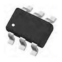
DCX114YK-7 Diodes Inc, DCX114YK-7 Datasheet - Page 9

DCX114YK-7
Manufacturer Part Number
DCX114YK-7
Description
Digital Transistors 300MW 10KW 47KW
Manufacturer
Diodes Inc
Datasheet
1.DCX124EK-7-F.pdf
(12 pages)
Specifications of DCX114YK-7
Configuration
Dual
Transistor Polarity
NPN/PNP
Typical Input Resistor
10 KOhms
Typical Resistor Ratio
0.213
Mounting Style
SMD/SMT
Package / Case
SC-74R-6
Peak Dc Collector Current
100 mA
Maximum Operating Temperature
+ 150 C
Minimum Operating Temperature
- 55 C
Lead Free Status / RoHS Status
Lead free / RoHS Compliant
Typical Curves – DCX114TK
DCX (xxxx) K
Document number: DS30350 Rev. 6 - 2
1,000
0.1
100
10
10
1
1
Fig. 24 Typical DC Current Gain vs. Collector Current
0
1
V = 0.2
T = 25°C
Fig. 26 Typical Capacitance Characteristics
Fig. 28 Input Voltage vs. Collector Current
O
A
I , COLLECTOR CURRENT (mA)
C
I , COLLECTOR CURRENT (mA)
10
C
V , REVERSE VOLTAGE (V)
R
20
10
C
obo
30
PNP Section
40
I = 0mA
E
100
50
www.diodes.com
9 of 12
0.001
0.001
0.01
100
0.01
0.1
10
0.1
1
1
0
0
Fig. 25 Typical Collector Emitter Saturation Voltage
T = 75°C
A
Fig. 27 Collector Current vs. Input Voltage
1
I /I = 10
C B
T = -25°C
A
I , COLLECTOR CURRENT (mA)
10
C
2
V , INPUT VOLTAGE (V)
T = 25°C
in
3
A
vs. Collector Current
T = 25 C
A
20
4
T = 75 C
°
A
5
°
30
6
T = -25 C
A
DCX (xxxx) K
7
°
40
8
© Diodes Incorporated
October 2008
9
10
50


