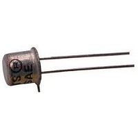
CR220 Vishay, CR220 Datasheet - Page 2

CR220
Manufacturer Part Number
CR220
Description
Current Regulator Diodes 2.2mA +/- 10%
Manufacturer
Vishay
Datasheet
1.CR220.pdf
(5 pages)
Specifications of CR220
Maximum Regulator Current
2.42 mA
Maximum Limiting Voltage
1.95 V
Maximum Peak Operating Voltage
135 V
Minimum Dynamic Impedance
0.37 MOhms
Minimum Knee Impedance
0.052 MOhms
Configuration
Single
Mounting Style
Through Hole
Package / Case
TO-226AA
Power Dissipation Pd
300mW
Diode Case Style
TO-206AA
No. Of Pins
2
Peak Reflow Compatible (260 C)
No
Current Rating
2.2A
Leaded Process Compatible
No
Forward Current If
2.2A
Mounting Type
Through Hole
Limiting Voltage (max)
1.95V
Knee Impedance (min)
52kohm
Package Type
TO-206AA
Operating Temperature Classification
Military
Lead Free Status / RoHS Status
Lead free / RoHS Compliant
Lead Free Status / RoHS Status
Contains lead / RoHS non-compliant, Lead free / RoHS Compliant
Available stocks
Company
Part Number
Manufacturer
Quantity
Price
Company:
Part Number:
CR220-E3
Manufacturer:
Vishay/Siliconix
Quantity:
135
Company:
Part Number:
CR2202AB
Manufacturer:
NIEC
Quantity:
30 000
CR160 Series
Vishay Siliconix
ABSOLUTE MAXIMUM RATINGS
Peak Operating Voltage
Reverse Current
Thermal Resistance (q
Notes:
a.
Notes:
a.
b.
c.
d.
e.
www.vishay.com
2
SPECIFICATIONS (T
Peak Operating Voltage
Reverse Voltage
Capacitance
Part Number
Derate 2.4 mW/_C above 25_C
Typical values are for DESIGN AID ONLY, not guaranteed nor subject to production testing.
Peak voltage at which I
Pulse test—steady state currents may vary.
Pulse test—steady state impedances may vary.
Min V
CR160
CR180
CR200
CR220
CR240
CR270
CR300
CR330
CR360
CR390
CR430
CR470
F
required to insure I
Parameter
. . . . . . . . . . . . . . . . . . . . . . . . . . . . . . . . . . . . . . . . . . . . .
JA
)
. . . . . . . . . . . . . . . . . . . . . . . . . . . . . . . . . . . . . . .
b
. . . . . . . . . . . . . . . . . . . . . . . . . . . . . . . . . .
1.440
1.620
1.800
1.980
2.160
2.430
2.700
2.970
3.240
3.510
3.870
4.230
Min
F
= 1.1 I
F
= 0.8 I
F(max)
Regulator
A
Current
V
F(min)
F
Nom
= 25_C UNLESS OTHERWISE NOTED)
mA
1.60
1.80
2.00
2.20
2.40
2.70
3.00
3.30
3.60
3.90
4.30
4.70
(I
= 25 V
.
F
)
.
c
Max
1.760
1.980
2.200
2.420
2.640
2.970
3.300
3.630
3.960
4.290
4.730
5.170
Symbol
P
V
C
OV
R
F
0.475
0.420
0.395
0.370
0.345
0.320
0.300
0.280
0.265
0.255
0.245
0.235
Dynamic Im-
Min
417_C/W
pedance
50 mA
V
100 V
F
(Z
MW
= 25 V
d
)
Typ
1.10
1.00
0.90
0.83
0.76
0.70
0.65
0.60
0.54
0.47
0.40
0.35
d
a
Test Conditions
Storage Temperature
Power Dissipation
V
F
I
= 25 V, f = 1 MHz
F
0.092
0.074
0.061
0.052
0.044
0.035
0.029
0.024
0.020
0.017
0.014
0.012
Min
Impedance
= 1.1 I
I
R
= 1 mA
V
Knee
F
(Z
MW
F(max)
= 6 V
k
)
Typ
0.40
0.34
0.28
0.25
0.22
0.19
0.16
0.14
0.13
0.12
0.10
0.09
a
. . . . . . . . . . . . . . . . . . . . . . . . . . . . . . . . . . . . . . . . .
a
. . . . . . . . . . . . . . . . . . . . . . . . . . . . . . . . . . .
Max
1.65
1.75
1.85
1.95
2.00
2.15
2.25
2.35
2.50
2.60
2.75
2.90
I
F
Voltage
Limiting
= 0.8 I
(V
V
L
Min
)
F(min)
100
Typ
0.70
0.75
0.80
0.85
0.90
0.95
1.00
1.05
1.10
1.17
1.25
1.32
e
a
Limits
Typ
S-40250—Rev. E, 15-Mar-04
135
0.8
6
Document Number: 70195
a
0_C v T
Temperature
Coefficient
ppm/_C
V
Max
F
Typ
−1000
−1125
(q
1000
−200
−400
−550
−730
−820
650
300
100
= 25 V
A
−55 to 200_C
0
1
v 100_C
)
a
300 mW
Unit
pF
V
V
NKO


