160MT140KPBF Vishay, 160MT140KPBF Datasheet - Page 2
160MT140KPBF
Manufacturer Part Number
160MT140KPBF
Description
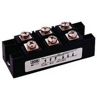
Bridge Rectifiers 1400 Volt 160 Amp
Manufacturer
Vishay
Specifications of 160MT140KPBF
Package / Case
INT-A-PAK
Product
Three Phase Bridge
Peak Reverse Voltage
1400 V
Max Surge Current
1500 A
Forward Voltage Drop
1.49 V
Maximum Reverse Leakage Current
10000 uA
Maximum Operating Temperature
+ 150 C
Length
94 mm
Width
35 mm
Height
30 mm
Mounting Style
Screw
Minimum Operating Temperature
- 40 C
Repetitive Reverse Voltage Vrrm Max
1.4kV
Leaded Process Compatible
Yes
Lead Free Status / RoHS Status
Lead free / RoHS Compliant


Thermal and Mechanical Specifications
Bulletin I27216 03/06
2
130-160MT..KPbF Series
Forward Conduction
ELECTRICAL SPECIFICATIONS
Voltage Ratings
T
T
R
R
T
wt
Type number
130-160MT..K
I
I
I
I
V
V
r
r
V
V
O
FSM
2
2
f1
f2
J
t
√t
stg
F(TO)1
F(TO)2
FM
INS
thJC
thCS
Parameter
Parameter
Maximum DC output current
@ Case temperature
Maximum peak, one-cycle forward,
non-repetitive surge current
Maximum I
Maximum I
Low level value of threshold voltage
High level value of threshold voltage
Low level value of forward slope resistance
High level value of forward slope resistance
Maximum forward voltage drop
RMS isolation voltage
Max. junction operating temperature range
Max. storage temperature range
Max. thermal resistance, junction to case
Max. thermal resistance, case to heatsink
Mounting torque ± 10%
Approximate weight
2
2
Voltage
t for fusing
√t for fusing
Code
120
100
140
160
80
V
to heatsink
to terminal
RRM
peak reverse voltage
, maximum repetitive
1200
1000
1400
1600
800
V
130 (160)
130MT.K
130MT.K
85 (62)
64000
64000
1130
1180
1000
5800
4500
4100
4000
0.78
0.99
4.59
4.17
1.63
0.16
0.93
0.18
1.08
950
-40 to 150
-40 to 150
4 to 6
3 to 4
0.03
176
160 (200)
160MT.K Units Conditions
160MT.K Units Conditions
102000
85 (60)
10200
1430
1500
1200
1260
9300
7200
6600
4000
0.12
0.73
0.15
0.88
0.81
1.04
3.52
3.13
1.49
repetitive peak rev. voltage
A
K/W
K/W
A
mΩ
Nm
°C
°C
°C
A
A
2
V
V
V
g
2
√s
V
s
RSM
A mounting compound is recommended and the
torque should be rechecked after a period of 3
hours to allow for the spread of the compound.
Lubricated threads.
120° Rect condunction angle per junction
120° Rect conduction angle
t = 10ms
t = 8.3ms
t = 10ms
t = 8.3ms
t = 10ms
t = 8.3ms
t = 10ms
t = 8.3ms
t = 0.1 to 10ms, no voltage reapplied
(16.7% x π x I
(I > π x I
(16.7% x π x I
(I > π x I
I
T
f = 50Hz, t = 1s
DC operation per module
DC operation per junction
120° Rect condunction angle per module
Per module
Mounting surface smooth, flat and greased
pk
J
, maximum non-
= 200A, T
= 25°C, all terminal shorted
1100
1300
1500
1700
900
V
F(AV)
F(AV)
J
No voltage
reapplied
100% V
reapplied
No voltage
reapplied
100% V
reapplied
), @ T
), @ T
F(AV)
F(AV)
= 25°C, t
< I < π x I
< I < π x I
J
J
RRM
RRM
max.
max.
p
= 400μs single junction
Initial T
F(AV)
F(AV)
www.irf.com
I
@ T
), @ T
), @ T
RRM
J
mA
= T
10
J
max.
max.
J
J
J
max.
max.
max.
Related parts for 160MT140KPBF
Image
Part Number
Description
Manufacturer
Datasheet
Request
R

Part Number:
Description:
FUSE 160A 690V AC TYPE T BRITISH
Manufacturer:
Cooper/Bussmann
Datasheet:

Part Number:
Description:
357-036-542-201 CARDEDGE 36POS DL .156 BLK LOPRO
Manufacturer:
Vishay
Datasheet:
Part Number:
Description:
357-036-542-201 CARDEDGE 36POS DL .156 BLK LOPRO
Manufacturer:
Vishay
Datasheet:
Part Number:
Description:
357-036-542-201 CARDEDGE 36POS DL .156 BLK LOPRO
Manufacturer:
Vishay
Datasheet:
Part Number:
Description:
357-036-542-201 CARDEDGE 36POS DL .156 BLK LOPRO
Manufacturer:
Vishay
Datasheet:
Part Number:
Description:
357-036-542-201 CARDEDGE 36POS DL .156 BLK LOPRO
Manufacturer:
Vishay
Datasheet:
Part Number:
Description:
357-036-542-201 CARDEDGE 36POS DL .156 BLK LOPRO
Manufacturer:
Vishay
Datasheet:
Part Number:
Description:
357-036-542-201 CARDEDGE 36POS DL .156 BLK LOPRO
Manufacturer:
Vishay
Datasheet:
Part Number:
Description:
357-036-542-201 CARDEDGE 36POS DL .156 BLK LOPRO
Manufacturer:
Vishay
Datasheet:
Part Number:
Description:
357-036-542-201 CARDEDGE 36POS DL .156 BLK LOPRO
Manufacturer:
Vishay
Datasheet:
Part Number:
Description:
357-036-542-201 CARDEDGE 36POS DL .156 BLK LOPRO
Manufacturer:
Vishay
Datasheet:
Part Number:
Description:
357-036-542-201 CARDEDGE 36POS DL .156 BLK LOPRO
Manufacturer:
Vishay
Datasheet:
Part Number:
Description:
357-036-542-201 CARDEDGE 36POS DL .156 BLK LOPRO
Manufacturer:
Vishay
Datasheet:
Part Number:
Description:
357-036-542-201 CARDEDGE 36POS DL .156 BLK LOPRO
Manufacturer:
Vishay
Datasheet:
Part Number:
Description:
357-036-542-201 CARDEDGE 36POS DL .156 BLK LOPRO
Manufacturer:
Vishay
Datasheet: