D3172MMA7361LC Freescale Semiconductor, D3172MMA7361LC Datasheet - Page 12
D3172MMA7361LC
Manufacturer Part Number
D3172MMA7361LC
Description
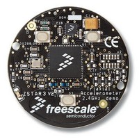
Acceleration Sensor Development Tools XYZ-AXIS DIGITAL ACCEL D
Manufacturer
Freescale Semiconductor
Specifications of D3172MMA7361LC
Acceleration
1.5 g
Sensing Axis
Triple Axis
Output Type
Digital
Interface Type
I2C, SPI
Operating Voltage
2 V to 3.4 V
Operating Current
47 uA
Sensitivity
64 LSB/g
For Use With/related Products
MMA7660FC
Lead Free Status / RoHS Status
Lead free / RoHS Compliant


$1B: Pulse Detection Threshold Limit Value (Read/Write)
PULSE DETECTION
In Pulse Mode, all functions can be active including measurements, level detections and pulse detection. There are two interrupt
pins available for detection of level and pulse conditions. The pulse detection has several timing windows associated with it. A
single pulse and a double pulse can be detected. Also freefall can be detected. The interrupt pins can be assigned to detect the
first pulse on one interrupt and the second pulse on the other interrupt. This is explained on
ing & Detecting Interrupts
By default all three axes are enabled and the detection range is 8g only. X and/or Y and/or Z can be disabled. There is a choice
between doing a detection for Motion detection vs. doing a detection for Freefall.
$18: Control 1 (Read/Write): Disable X, Y or Z for Pulse Detection
This allows the user to define how many axes to use for detection. All axes are enabled by default. To disable write 1
XDA: Disable X
YDA: Disable Y
ZDA: Disable Z.
$19: Control 2 (Read/Write): Motion Detection (OR condition) or Freefall Detection (AND condition)
PDPL
0: Pulse detection polarity is positive and detecting condition is OR 3 axes.
1: Pulse detection polarity is negative and detecting condition is AND 3 axes.
CASE 1: Single Pulse Motion Detection: X or Y or Z > Pulse Threshold for Time < Pulse Duration
For motion detection with single pulse the device must be in pulse mode. PDPL in Register $19 =0 for “OR” motion condition.
The Pulse threshold must be set in Register $1B and the pulse duration time window must also be set using Register $1C. The
pulse must be detected before the time window closes for the interrupt to trigger.
$1C: Pulse Duration Value (Read/Write)
12
MMA7455L
PDTH[7]
DFBW
PD[7]
D7
D7
D7
D7
0
0
--
0
0
PDTH[6]
THOPT
PD[6]
D6
D6
D6
D6
0
--
0
0
0
section.
PDTH[5]
PD[5]
ZDA
D5
D5
D5
D5
0
--
0
0
0
PDTH[4]
PD[4]
YDA
D4
D4
D4
D4
--
0
0
0
0
PDTH[3]
PD[3]
XDA
D3
D3
D3
D3
0
--
0
0
0
INTREG[1]
PDTH[2]
DRVO
PD[2]
D2
D2
D2
D2
0
0
0
0
INTREG[0]
PDTH[1]
PDPL
PD[1]
D1
D1
Page
D1
D1
0
0
0
0
15, under the
Freescale Semiconductor
PDTH[0]
INTPIN
LDPL
PD[0]
D0
D0
D0
D0
1
0
0
0
Assigning, Clear-
Reg $1C
Function
Function
Reg $19
Reg $1B
Reg $18
Function
Function
Default
Default
Default
Default
Sensors
Related parts for D3172MMA7361LC
Image
Part Number
Description
Manufacturer
Datasheet
Request
R

Part Number:
Description:
Manufacturer:
Freescale Semiconductor, Inc
Datasheet:
Part Number:
Description:
Manufacturer:
Freescale Semiconductor, Inc
Datasheet:
Part Number:
Description:
Manufacturer:
Freescale Semiconductor, Inc
Datasheet:
Part Number:
Description:
Manufacturer:
Freescale Semiconductor, Inc
Datasheet:
Part Number:
Description:
Manufacturer:
Freescale Semiconductor, Inc
Datasheet:
Part Number:
Description:
Manufacturer:
Freescale Semiconductor, Inc
Datasheet:
Part Number:
Description:
Manufacturer:
Freescale Semiconductor, Inc
Datasheet:
Part Number:
Description:
Manufacturer:
Freescale Semiconductor, Inc
Datasheet:
Part Number:
Description:
Manufacturer:
Freescale Semiconductor, Inc
Datasheet:
Part Number:
Description:
Manufacturer:
Freescale Semiconductor, Inc
Datasheet:
Part Number:
Description:
Manufacturer:
Freescale Semiconductor, Inc
Datasheet:
Part Number:
Description:
Manufacturer:
Freescale Semiconductor, Inc
Datasheet:
Part Number:
Description:
Manufacturer:
Freescale Semiconductor, Inc
Datasheet:
Part Number:
Description:
Manufacturer:
Freescale Semiconductor, Inc
Datasheet:
Part Number:
Description:
Manufacturer:
Freescale Semiconductor, Inc
Datasheet: