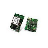
RK-WI.USB-DTS-R Radiotronix, RK-WI.USB-DTS-R Datasheet - Page 12

RK-WI.USB-DTS-R
Manufacturer Part Number
RK-WI.USB-DTS-R
Description
RF Modules & Development Tools Wi.USB-DTS Dev Kit w/ Rohs Base St
Manufacturer
Radiotronix
Datasheet
1.RK-WI.USB-DTS-R.pdf
(18 pages)
Specifications of RK-WI.USB-DTS-R
Lead Free Status / RoHS Status
Lead free / RoHS Compliant
Other names
RK-WIUSB-DTS-R
WI.USB-DTS-R DATASHEET
The “Set TX Diag” button switches the transmitter on using the channel and mode selected in the channel
selector and transceiver mode controls. A “…1010101010101…” bit pattern is transmitted for bit error testing
with another system or RF carrier analysis.
4.2.3. Receive Diagnostic
Receive Diagnostic consists of four radio buttons which select the transmit channel. Low, Mid and High are
quick reference buttons which can be used to select the lowest, the middle, or the highest channel. Any
specific channel can be selected by using the controls above the “Set RX Diag” button.
The “Set RX Diag” button switches on the receiver using the channel and mode selected in the channel
selector and transceiver mode controls. Additionally, the module enters the diagnostic bit error test.
If a “…1010101010101…” bit pattern is received at the frequency and baud rate set up in the relevant
registers, the BER test will return the number and percent of bit errors. This information is displayed in the
panel below the “Set RX Diag” button. If no transmission is present, or the transmission is at the wrong
frequency or data rate, the module may enter an infinite loop waiting for the beginning of the data. In this
case, the module should be powered down and back up to return the module to its normal operating mode.
11


