EA-EDU-001 Embedded Artists, EA-EDU-001 Datasheet - Page 9
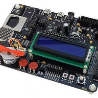
EA-EDU-001
Manufacturer Part Number
EA-EDU-001
Description
MCU, MPU & DSP Development Tools LPC2148 EDUCATION BRD
Manufacturer
Embedded Artists
Specifications of EA-EDU-001
Processor To Be Evaluated
LPC2148
Data Bus Width
16 bit, 32 bit
Interface Type
I2C, SPI, UART
Core
ARM7TDMI-S
Dimensions
156 mm x 110 mm
Maximum Operating Temperature
+ 85 C
Operating Supply Voltage
3.3 V
Lead Free Status / RoHS Status
Lead free / RoHS Compliant


NXP Semiconductors
Table 3.
LPC2141_42_44_46_48_4
Product data sheet
Symbol
P0.18/CAP1.3/
MISO1/MAT1.3
P0.19/MAT1.2/
MOSI1/CAP1.2
P0.20/MAT1.3/
SSEL1/EINT3
P0.21/PWM5/
AD1.6/CAP1.3
P0.22/AD1.7/
CAP0.0/MAT0.0
P0.23/V
P0.25/AD0.4/
AOUT
P0.28/AD0.1/
CAP0.2/MAT0.2
P0.29/AD0.2/
CAP0.3/MAT0.3
P0.30/AD0.3/
EINT3/CAP0.0
BUS
Pin description
Pin
53
54
55
1
2
58
9
13
14
15
[4]
[4]
[5]
[1]
[1]
[2]
[1]
[4]
[4]
[4]
…continued
Type
I/O
I
I/O
O
I/O
O
I/O
I
I/O
O
I
I
I/O
O
I
I
I/O
I
I
O
I/O
I
I/O
I
O
I/O
I
I
O
I/O
I
I
O
I/O
I
I
I
Description
P0.18 — General purpose input/output digital pin (GPIO).
CAP1.3 — Capture input for Timer 1, channel 3.
MISO1 — Master In Slave Out for SSP. Data input to SPI master or data
output from SSP slave.
MAT1.3 — Match output for Timer 1, channel 3.
P0.19 — General purpose input/output digital pin (GPIO).
MAT1.2 — Match output for Timer 1, channel 2.
MOSI1 — Master Out Slave In for SSP. Data output from SSP master or data
input to SSP slave.
CAP1.2 — Capture input for Timer 1, channel 2.
P0.20 — General purpose input/output digital pin (GPIO).
MAT1.3 — Match output for Timer 1, channel 3.
SSEL1 — Slave Select for SSP. Selects the SSP interface as a slave.
EINT3 — External interrupt 3 input.
P0.21 — General purpose input/output digital pin (GPIO).
PWM5 — Pulse Width Modulator output 5.
AD1.6 — ADC 1, input 6. Available in LPC2144/46/48 only.
CAP1.3 — Capture input for Timer 1, channel 3.
P0.22 — General purpose input/output digital pin (GPIO).
AD1.7 — ADC 1, input 7. Available in LPC2144/46/48 only.
CAP0.0 — Capture input for Timer 0, channel 0.
MAT0.0 — Match output for Timer 0, channel 0.
P0.23 — General purpose input/output digital pin (GPIO).
V
Note: This signal must be HIGH for USB reset to occur.
P0.25 — General purpose input/output digital pin (GPIO).
AD0.4 — ADC 0, input 4.
AOUT — DAC output. Available in LPC2142/44/46/48 only.
P0.28 — General purpose input/output digital pin (GPIO).
AD0.1 — ADC 0, input 1.
CAP0.2 — Capture input for Timer 0, channel 2.
MAT0.2 — Match output for Timer 0, channel 2.
P0.29 — General purpose input/output digital pin (GPIO).
AD0.2 — ADC 0, input 2.
CAP0.3 — Capture input for Timer 0, channel 3.
MAT0.3 — Match output for Timer 0, channel 3.
P0.30 — General purpose input/output digital pin (GPIO).
AD0.3 — ADC 0, input 3.
EINT3 — External interrupt 3 input.
CAP0.0 — Capture input for Timer 0, channel 0.
BUS
Rev. 04 — 17 November 2008
— Indicates the presence of USB bus power.
LPC2141/42/44/46/48
Single-chip 16-bit/32-bit microcontrollers
© NXP B.V. 2008. All rights reserved.
9 of 40
Related parts for EA-EDU-001
Image
Part Number
Description
Manufacturer
Datasheet
Request
R

Part Number:
Description:
MCU, MPU & DSP Development Tools LPC2103 EDUCATION BRD
Manufacturer:
Embedded Artists
Datasheet:

Part Number:
Description:
MCU, MPU & DSP Development Tools LPC2138 EDUCATION BRD
Manufacturer:
Embedded Artists
Datasheet:

Part Number:
Description:
MCU, MPU & DSP Development Tools EXPERIMENT EXPANSION BRD
Manufacturer:
Embedded Artists
Datasheet:

Part Number:
Description:
HEATSINK FOR TO-220 BLACK
Manufacturer:
Ohmite
Datasheet:

Part Number:
Description:
HEATSINK FOR TO-220 BLACK
Manufacturer:
Ohmite
Datasheet:

Part Number:
Description:
HEATSINK FOR TO-220 BLACK
Manufacturer:
Ohmite
Datasheet:

Part Number:
Description:
LCD Graphic Display Modules & Accessories Pure Green Backlight For DOG-M Series
Manufacturer:
ELECTRONIC ASSEMBLY
Datasheet:

Part Number:
Description:
LCD Graphic Display Modules & Accessories Grn LED Backlight For DOG-XL Series
Manufacturer:
ELECTRONIC ASSEMBLY
Datasheet:
Part Number:
Description:
LCD Graphic Display Modules & Accessories Green LED Backlight For DOG-L Series
Manufacturer:
ELECTRONIC ASSEMBLY
Datasheet:

Part Number:
Description:
KIT LPC3141 SODIMM 66X48 200POS
Manufacturer:
Embedded Artists
Datasheet:
Part Number:
Description:
KIT LPC3152 SODIMM 66X48 200POS
Manufacturer:
Embedded Artists
Datasheet:
Part Number:
Description:
BOARD OEM W/LPC2478 MCU
Manufacturer:
Embedded Artists
Datasheet:
Part Number:
Description:
KIT LPC3250 259 WITH QVGA
Manufacturer:
Embedded Artists
Datasheet: