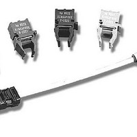
HFBR-0536Z Avago Technologies US Inc., HFBR-0536Z Datasheet - Page 7

HFBR-0536Z
Manufacturer Part Number
HFBR-0536Z
Description
KIT EVAL FIBER OPTICS 32MBD
Manufacturer
Avago Technologies US Inc.
Specifications of HFBR-0536Z
Main Purpose
Interface, Fiber Optics
Embedded
No
Utilized Ic / Part
HFBR-1527Z, HFBR-2526Z
Primary Attributes
650nm, 32MBd, TTL
Operating Voltage
5 V
Description/function
Versatile Fiber Optic Evaluation Kit
Maximum Operating Temperature
+ 85 C
Minimum Operating Temperature
- 40 C
Operating Current
6.2 mA
Silicon Manufacturer
Avago
Kit Application Type
Communication & Networking
Peak Reflow Compatible (260 C)
Yes
Leaded Process Compatible
Yes
Rohs Compliant
Yes
For Use With/related Products
HFBR-1527Z, HFBR-2526Z
Lead Free Status / RoHS Status
Lead free / RoHS Compliant
Secondary Attributes
-
Lead Free Status / Rohs Status
Details
Other names
516-2321
Electrical/Optical Characteristics 0 to 70°C, unless otherwise stated.
Notes:
1. 1.6 mm below seating plane.
2. Typical data is at 25°C.
3. Optical Power measured at the end of 0.5 meter of 1 mm diameter plastic or 200 µm diameter hard clad silica optical fiber with a large area
4. Typical value measured from junction to PC board solder joint for horizontal mount package, HFBR-1527Z. θ
5. Optical rise and fall times can be reduced with the appropriate driver circuit; refer to Application Note 1066.
6. Pins 5 and 8 are primarily for mounting and retaining purposes, but are electrically connected; pins 3 and 4 are electrically unconnected. It is
7. Refer to the Versatile Link Family Fiber Optic Cable and Connectors Technical Data Sheet for cable connector options for 1 mm plastic optical
8. The LED current peaking necessary for high frequency circuit design contributes to electromagnetic interference (EMI). Care must be taken in
7
Parameter
Transmitter Output
Optical Power, 1 mm POF
Transmitter Output
Optical Power, 1 mm POF
Transmitter Output
Optical Power,
200 µm HCS
Output Optical Power
Temperature Coefficient
Peak Emission Wavelength
Peak Wavelength
Temperature Coefficient
Spectral Width
Forward Voltage
Forward Voltage
Temperature Coefficient
Transmitter Numerical
Aperture
Thermal Resistance,
Junction to Case
Reverse Input Breakdown
Voltage
Diode Capacitance
Unpeaked Optical Rise
Time, 10% - 90%
Unpeaked Optical Fall
Time, 90% - 10%
detector.
30°C/W higher for vertical mount package, HFBR-1537Z.
recommended that pins 3, 4, 5, and 8 all be connected to ground to reduce coupling of electrical noise.
fiber and 200 µm HCS fiber.
circuit board layout to minimize emissions for compliance with governmental EMI emissions regulations. Refer to Application Note 1066 for
design guidelines.
®
Symbol
FWHM
∆P
∆V
NA
λ
∆λ
V
∆T
∆T
∆T
θ
C
P
P
P
V
t
t
BR
PK
jc
O
r
f
T
T
T
F
T
F
-10.4
-14.6
-15.5
Min.
-9.5
-6.0
-6.9
640
1.8
3.0
Typ.
-13.0
-0.02
0.12
-7.0
-3.0
650
-1.8
140
2.1
0.5
21
13
60
12
9
[2]
-10.5
-10.0
Max.
-4.8
-4.3
-0.5
-0.0
660
2.4
nm/°C
mV/°C
dB/°C
°C/W
dBm
dBm
dBm
Unit
nm
nm
pF
ns
ns
V
V
I
I
I
F,dc
F,dc
F,dc
Half Maximum
jc
I
f = 100 kHz
f = 100 kHz
Full Width,
F,dc
= 20 mA, 25°C
= 60 mA, 25°C
= 60 mA, 25°C
I
I
I
is approximately
f = 1 MHz
Condition
F
F
F
V
= 60 mA
= 60 mA
= 60 mA
0-70°C
0-70°C
0-70°C
= -10 µA
F
= 0 V,
Figure 1
Figure 1
Note 5
Note 5
Note 3
Note 3
Note 3
Note 4
Note


