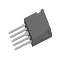
FBO40-12N IXYS, FBO40-12N Datasheet

FBO40-12N
Manufacturer Part Number
FBO40-12N
Description
DIODE BRIDGE 1PHASE I4-PAC-5
Manufacturer
IXYS
Datasheet
1.FBO40-12N.pdf
(2 pages)
Specifications of FBO40-12N
Voltage - Peak Reverse (max)
1200V
Current - Dc Forward (if)
40A
Diode Type
Single Phase
Speed
Standard Recovery >500ns, > 200mA (Io)
Mounting Type
Through Hole
Package / Case
ISOPLUS i4-PAC™
Phase Type
Single Phase
Number Of Elements
1
Peak Rep Rev Volt
1.2kV
Peak Non-repetitive Surge Current (max)
250A
Avg. Forward Curr (max)
20A
Rev Curr
20uA
Forward Voltage
1.2V
Package Type
ISOPLUS i4-Pac
Operating Temp Range
-55C to 150C
Pin Count
5
Mounting
Through Hole
Operating Temperature Classification
Military
Vrrm, (v)
1200
Vvrms, (v)
400
Idavm, (a)
40
@ Tc, (°c)
90
Ifsm, 10 Ms, Tvj = 45°c, (a)
250
Vt0, (v)
0.83
Rt, (mohms)
10
Tvjm, (°c)
150
Rthjc, Per Chip, (k/w)
2.30
Rthjh, Per Chip, (k/w)
2.90
Package Style
ISOPLUS i4-PAC (5 - Lead)
Lead Free Status / RoHS Status
Lead free / RoHS Compliant
Reverse Recovery Time (trr)
-
Lead Free Status / Rohs Status
Compliant
Available stocks
Company
Part Number
Manufacturer
Quantity
Price
Company:
Part Number:
FBO40-12N
Manufacturer:
IXYS
Quantity:
20 000
Single Phase
Rectifier Bridge
in ISOPLUS i4-PAC
Symbol
V
I
I
I
P
Symbol
V
I
Data according to IEC 60747 refer to a single diode unless otherwise stated
IXYS reserves the right to change limits, test conditions and dimensions.
© 2001 IXYS All rights reserved
Rectifier Bridge
FAV
D(AV)M
FSM
R
R
R
RRM
tot
F
thJC
thJS
Conditions
T
T
T
T
Conditions
I
V
(per diode)
F
C
C
VJ
C
R
= 25 A; T
= 90°C; sine 180° (per diode)
= 90°C
= 25°C
= V
= 25°C; t = 10 ms; sine 50 Hz
RRM
; T
T
T
VJ
VJ
VJ
VJ
= 25°C
= 125°C
= 25°C
= 125°C
TM
(per diode)
(T
Advanced Technical Information
VJ
= 25 C, unless otherwise specified)
min.
FBO40-12N
Characteristic Values
Maximum Ratings
typ.
1.1
1.1
0.4
2.9
1200
250
20
40
55
max.
1.2
2.3 K/W
20
K/W
mA
W
µA
V
A
A
A
V
V
V
I
I
Features
• rectifier diodes for line frequency
• ISOPLUS i4-PAC
Applications
• single phase mains rectifiers
• power factor correction in conjunction
D(AV)M
FSM
- isolated back surface
- low coupling capacity between pins
- enlarged creepage towards heatsink
- application friendly pinout
- high reliability
- industry standard outline
with boost chopper (FID.../FMD... type)
RRM
and heatsink
1
5
= 1200 V
= 40 A
= 250 A
TM
package
1 - 2
Related parts for FBO40-12N
FBO40-12N Summary of contents
Page 1
... R thJS Data according to IEC 60747 refer to a single diode unless otherwise stated IXYS reserves the right to change limits, test conditions and dimensions. © 2001 IXYS All rights reserved Advanced Technical Information FBO40-12N Maximum Ratings 1200 20 40 250 (per diode) 55 ...
Page 2
... pin - backside metal S A Weight Dimensions 0.0394") Maximum Ratings -55...+150 C -55...+125 C 2500 V~ 20...120 N Characteristic Values min. typ. max 1 FBO 40-12N © 2000 IXYS All rights reserved ...


