100MT160PAPBF Vishay, 100MT160PAPBF Datasheet - Page 2
100MT160PAPBF
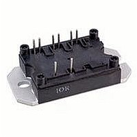
Manufacturer Part Number
100MT160PAPBF
Description
DIODE BRDG 3PHS 1600V 100A INTPK
Manufacturer
Vishay
Specifications of 100MT160PAPBF
Voltage - Peak Reverse (max)
1600V
Current - Dc Forward (if)
100A
Diode Type
Three Phase
Speed
Standard Recovery >500ns, > 200mA (Io)
Mounting Type
PCB
Package / Case
7-MTPA
Product
Three Phase Bridge
Peak Reverse Voltage
1600 V
Max Surge Current
470 A
Forward Voltage Drop
1.51 V
Maximum Reverse Leakage Current
5000 uA
Maximum Operating Temperature
+ 150 C
Length
63.5 mm
Width
32.5 mm
Height
16 mm
Mounting Style
SMD/SMT
Minimum Operating Temperature
- 40 C
No. Of Phases
Three
Repetitive Reverse Voltage Vrrm Max
1.6V
Forward Current If(av)
100A
Forward Voltage Vf Max
1.51V
Diode Mounting Type
Through Hole
Lead Free Status / RoHS Status
Lead free / RoHS Compliant
Reverse Recovery Time (trr)
-
Lead Free Status / RoHS Status
Lead free / RoHS Compliant, Lead free / RoHS Compliant
Other names
Q3744328
VS-100MT160PAPBF
VS-100MT160PAPBF
VS100MT160PAPBF
VS100MT160PAPBF
VS-100MT160PAPBF
VS-100MT160PAPBF
VS100MT160PAPBF
VS100MT160PAPBF


40MT1.0P.PbF, 70MT1.0P.PbF, 100MT1.0P.PbF Series
Vishay High Power Products
ELECTRICAL SPECIFICATIONS
www.vishay.com
2
VOLTAGE RATINGS
TYPE NUMBER
40MT140P, 70MT140P, 100MT140P
40MT160P, 70MT160P, 100MT160P
FORWARD CONDUCTION
PARAMETER
Maximum DC output current
at case temperature
Maximum peak, one cycle
forward, non-repetitive on state
surge current
Maximum I
Maximum I
Value of threshold voltage
Slope resistance
Maximum forward voltage drop
INSULATION TABLE
PARAMETER
RMS insulation voltage
THERMAL AND MECHANICAL SPECIFICATIONS
PARAMETER
Maximum junction operating
temperature range
Maximum storage
temperature range
Maximum thermal resistance,
junction to case
Maximum thermal resistance,
case to heatsink per module
Mounting torque to heatsink
± 10 %
Approximate weight
2
2
t for fusing
t for fusing
SYMBOL
SYMBOL
SYMBOL
R
V
R
V
T
I
V
FSM
I
F(TO)
thCS
I
T
thJC
I
2
INS
Stg
r
2
FM
O
J
REVERSE VOLTAGE
t
t
For technical questions, contact:
t
VOLTAGE CODE
T
DC operation per module
DC operation per junction
120° rect. condunction angle per module
120° rect. condunction angle per junction
Mounting surface smooth, flat and greased
Heatsink compound thermal conductivity = 0.42 W/mK
A mounting compound is recommended and the torque
should be rechecked after a period of 3 hours to allow
for the spread of the compound.
Lubricated threads
120° rect. to conduction angle
t = 10 ms
t = 8.3 ms
t = 10 ms
t = 8.3 ms
t = 10 ms
t = 8.3 ms
t = 10 ms
t = 8.3 ms
t = 0.1 ms to 10 ms, no voltage reapplied
T
T
(40MT, I
J
140
160
J
J
(Power Module), 45 A to 100 A
V
= 25 °C, all terminal shorted, f = 50 Hz, t = 1 s
maximum
= 25 °C; t
pk
Three Phase Bridge
= 40 A) (70MT, I
p
= 400 μs single junction
No voltage
reapplied
100 % V
reapplied
No voltage
reapplied
100 % V
reapplied
TEST CONDITIONS
TEST CONDITIONS
TEST CONDITIONS
REVERSE VOLTAGE
REPETITIVE PEAK
V
RRM
RRM
RRM
pk
, MAXIMUM
indmodules@vishay.com
1400
1600
= 70 A) (100MT, I
V
Initial
T
J
= T
J
maximum
pk
NON-REPETITIVE PEAK
= 100 A)
V
RSM
, MAXIMUM
1500
1700
40MT
40MT
40MT
V
3650
0.78
14.8
1.45
0.27
0.38
2.25
100
270
280
225
240
365
325
253
240
1.6
45
- 40 to 150
- 40 to 125
70MT
70MT
70MT
Document Number: 94538
7240
0.23
1.38
0.29
1.76
0.82
1.45
3500
380
398
320
335
724
660
512
467
9.5
75
80
0.1
65
4
Revision: 10-Mar-10
I
100MT
100MT
100MT
10 130
RRM
AT T
1013
0.19
0.75
1.51
1.14
0.22
1.29
100
450
470
380
400
920
600
665
8.1
80
MAXIMUM
J
mA
= 150 °C
5
UNITS
UNITS
UNITS
A
K/W
A
m
Nm
°C
°C
2
A
V
V
V
g
2
s
s
Related parts for 100MT160PAPBF
Image
Part Number
Description
Manufacturer
Datasheet
Request
R

Part Number:
Description:
357-036-542-201 CARDEDGE 36POS DL .156 BLK LOPRO
Manufacturer:
Vishay
Datasheet:
Part Number:
Description:
357-036-542-201 CARDEDGE 36POS DL .156 BLK LOPRO
Manufacturer:
Vishay
Datasheet:
Part Number:
Description:
357-036-542-201 CARDEDGE 36POS DL .156 BLK LOPRO
Manufacturer:
Vishay
Datasheet:
Part Number:
Description:
357-036-542-201 CARDEDGE 36POS DL .156 BLK LOPRO
Manufacturer:
Vishay
Datasheet:
Part Number:
Description:
357-036-542-201 CARDEDGE 36POS DL .156 BLK LOPRO
Manufacturer:
Vishay
Datasheet:
Part Number:
Description:
357-036-542-201 CARDEDGE 36POS DL .156 BLK LOPRO
Manufacturer:
Vishay
Datasheet:
Part Number:
Description:
357-036-542-201 CARDEDGE 36POS DL .156 BLK LOPRO
Manufacturer:
Vishay
Datasheet:
Part Number:
Description:
357-036-542-201 CARDEDGE 36POS DL .156 BLK LOPRO
Manufacturer:
Vishay
Datasheet:
Part Number:
Description:
357-036-542-201 CARDEDGE 36POS DL .156 BLK LOPRO
Manufacturer:
Vishay
Datasheet:
Part Number:
Description:
357-036-542-201 CARDEDGE 36POS DL .156 BLK LOPRO
Manufacturer:
Vishay
Datasheet:
Part Number:
Description:
357-036-542-201 CARDEDGE 36POS DL .156 BLK LOPRO
Manufacturer:
Vishay
Datasheet:
Part Number:
Description:
357-036-542-201 CARDEDGE 36POS DL .156 BLK LOPRO
Manufacturer:
Vishay
Datasheet:
Part Number:
Description:
357-036-542-201 CARDEDGE 36POS DL .156 BLK LOPRO
Manufacturer:
Vishay
Datasheet:
Part Number:
Description:
357-036-542-201 CARDEDGE 36POS DL .156 BLK LOPRO
Manufacturer:
Vishay
Datasheet:
Part Number:
Description:
357-036-542-201 CARDEDGE 36POS DL .156 BLK LOPRO
Manufacturer:
Vishay
Datasheet: