36MT80 Vishay, 36MT80 Datasheet - Page 2
36MT80
Manufacturer Part Number
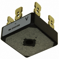
36MT80
Description
RECT BRIDGE 3-PHA 800V 35A D-63
Manufacturer
Vishay
Datasheet
1.36MT120.pdf
(7 pages)
Specifications of 36MT80
Voltage - Peak Reverse (max)
800V
Current - Dc Forward (if)
35A
Diode Type
Three Phase
Speed
Standard Recovery >500ns, > 200mA (Io)
Mounting Type
QC Terminal
Package / Case
D-63
Product
Three Phase Bridge
Peak Reverse Voltage
800 V
Max Surge Current
500 A
Forward Voltage Drop
1.19 V
Maximum Reverse Leakage Current
200 uA
Maximum Operating Temperature
+ 150 C
Length
28.5 mm
Width
28.5 mm
Height
10 mm
Mounting Style
Stud
Minimum Operating Temperature
- 55 C
Lead Free Status / RoHS Status
Lead free / RoHS Compliant
Reverse Recovery Time (trr)
-
Lead Free Status / Rohs Status
Lead free / RoHS Compliant
Other names
*36MT80
VS-36MT80
VS-36MT80
VS36MT80
VS36MT80
VS-36MT80
VS-36MT80
VS36MT80
VS36MT80
Available stocks
Company
Part Number
Manufacturer
Quantity
Price

Part Number:
36MT80
Manufacturer:
IR
Quantity:
20 000


26MT../36MT..Series
Vishay High Power Products
www.vishay.com
2
FORWARD CONDUCTION
PARAMETER
Maximum DC output current
at T
Maximum peak, one-cycle
non-repetitive forward current
Initial T
Maximum I
Initial T
Maximum I
Low-level of threshold voltage
High-level of threshold voltage
Low-level forward slope resistance
High-level forward slope resistance
Maximum forward voltage drop
Maximum DC reverse current
RMS isolation voltage
THERMAL AND MECHANICAL SPECIFICATIONS
PARAMETER
Maximum junction temperature range
Maximum storage temperature range
Maximum thermal resistance, junction to case
Maximum thermal resistance, case to heatsink
Approximate weight
Mounting torque ± 10 %
C
J
J
= T
= T
2
2
J
t for fusing
J
√t for fusing
maximum
maximum
SYMBOL
V
V
F(TO)1
F(TO)2
I
V
I
V
For technical questions, contact: ind-modules@vishay.com
I
RRM
FSM
I
2
r
r
I
INS
O
2
t1
t2
FM
√t
t
120° rect. conduction angle
t = 10 ms
t = 8.3 ms
t = 10 ms
t = 8.3 ms
t = 10 ms
t = 8.3 ms
t = 10 ms
t = 8.3 ms
I
(16.7 % x π x I
( I > π x I
(16.7 % x π x I
( I > π x I
T
T
T
SYMBOL
2
J
J
J
t for time t
R
R
= 25 °C, I
= 25 °C, per junction at rated V
= 25 °C, all terminal shorted; f = 50 Hz, t = 1 s
T
T
thCS
thJC
Stg
Three Phase Bridge
J
Power Modules
F(AV)
F(AV)
x
FM
= I
), at T
), at T
DC operation per bridge
(based on total power loss of bridge)
Mounting surface, smooth, flat and
greased
Bridge to heatsink with screw M4
F(AV)
F(AV)
= 40 Apk - per single junction
2
TEST CONDITIONS
100 % V
100 % V
√t x √t
No voltage
No voltage
reapplied
reapplied
reapplied
reapplied
J
J
< I < π x I
< I < π x I
maximum
maximum
x
TEST CONDITIONS
; 0.1 ≤ t
RRM
RRM
F(AV)
F(AV)
x
Initial T
≤ 10 ms, V
), at T
), at T
RRM
J
J
J
= T
maximum
maximum
J
RRM
maximum
= 0 V
26MT
26MT
6360
0.88
1.26
1.13
1.42
360
375
300
314
635
580
450
410
7.9
5.2
0.2
25
70
- 55 to 150
- 55 to 150
Document Number: 93565
2700
100
2.0
20
Revision: 25-May-07
11 300
36MT
36MT
1130
1030
0.86
1.03
1.19
1.35
475
500
400
420
800
730
6.3
5.0
0.2
35
60
UNITS
UNITS
A
K/W
A
mΩ
Nm
°C
µA
°C
A
A
2
V
V
V
g
2
√s
s
Related parts for 36MT80
Image
Part Number
Description
Manufacturer
Datasheet
Request
R

Part Number:
Description:
357-036-542-201 CARDEDGE 36POS DL .156 BLK LOPRO
Manufacturer:
Vishay
Datasheet:
Part Number:
Description:
357-036-542-201 CARDEDGE 36POS DL .156 BLK LOPRO
Manufacturer:
Vishay
Datasheet:
Part Number:
Description:
357-036-542-201 CARDEDGE 36POS DL .156 BLK LOPRO
Manufacturer:
Vishay
Datasheet:
Part Number:
Description:
357-036-542-201 CARDEDGE 36POS DL .156 BLK LOPRO
Manufacturer:
Vishay
Datasheet:
Part Number:
Description:
357-036-542-201 CARDEDGE 36POS DL .156 BLK LOPRO
Manufacturer:
Vishay
Datasheet:
Part Number:
Description:
357-036-542-201 CARDEDGE 36POS DL .156 BLK LOPRO
Manufacturer:
Vishay
Datasheet:
Part Number:
Description:
357-036-542-201 CARDEDGE 36POS DL .156 BLK LOPRO
Manufacturer:
Vishay
Datasheet:
Part Number:
Description:
357-036-542-201 CARDEDGE 36POS DL .156 BLK LOPRO
Manufacturer:
Vishay
Datasheet:
Part Number:
Description:
357-036-542-201 CARDEDGE 36POS DL .156 BLK LOPRO
Manufacturer:
Vishay
Datasheet:
Part Number:
Description:
357-036-542-201 CARDEDGE 36POS DL .156 BLK LOPRO
Manufacturer:
Vishay
Datasheet:
Part Number:
Description:
357-036-542-201 CARDEDGE 36POS DL .156 BLK LOPRO
Manufacturer:
Vishay
Datasheet:
Part Number:
Description:
357-036-542-201 CARDEDGE 36POS DL .156 BLK LOPRO
Manufacturer:
Vishay
Datasheet:
Part Number:
Description:
357-036-542-201 CARDEDGE 36POS DL .156 BLK LOPRO
Manufacturer:
Vishay
Datasheet:
Part Number:
Description:
357-036-542-201 CARDEDGE 36POS DL .156 BLK LOPRO
Manufacturer:
Vishay
Datasheet:
Part Number:
Description:
357-036-542-201 CARDEDGE 36POS DL .156 BLK LOPRO
Manufacturer:
Vishay
Datasheet: