HLA22507Z750R0KJ Vishay, HLA22507Z750R0KJ Datasheet
HLA22507Z750R0KJ
Specifications of HLA22507Z750R0KJ


Related parts for HLA22507Z750R0KJ

HLA22507Z750R0KJ Summary of contents
Page 1
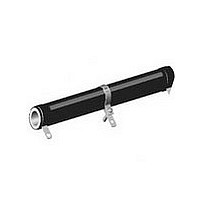
... Historical Part Number Example: HLA-225-07Z 200 Ω J01 (will continue to be accepted) HLA-225 07Z HISTORICAL MODEL TERMINAL/FINISH * Pb containing terminations are not RoHS compliant, exemptions may apply www.vishay.com For technical questions, contact: ww2bresistors@vishay.com 80 Wirewound Resistors, FEATURES • Adjustable resistor or voltage divider • High temperature silicon coating • Can be used to quickly obtain odd resistance values • ...
Page 2
... MOUNTING HARDWARE HLA resistors use same mounting hardware as standard HL resistors, see HL data sheet for mounting hardware dimensions. Document Number: 30211 For technical questions, contact: ww2bresistors@vishay.com Revision: 13-Jul-07 Wirewound Resistors, DIMENSIONS in inches [millimeters] TERMINAL CORE DIMENSIONS SETBACK ± ...
Page 3
... Vishay disclaims any and all liability arising out of the use or application of any product described herein or of any information provided herein to the maximum extent permitted by law. The product specifications do not expand or otherwise modify Vishay’ ...