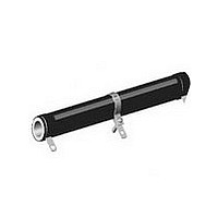
HLA
Vishay Dale
Note
(1)
MATERIAL SPECIFICATIONS
Element: Copper-nickel
depending on resistance range
Core: Ceramic, steatite
Coating: Special high temperature silicone
* Pb containing terminations are not RoHS compliant, exemptions may apply
www.vishay.com
80
additional P/N’s)
(See “Standard
STANDARD ELECTRICAL SPECIFICATIONS
GLOBAL
MODEL
HLA012
HLA020
HLA025
HLA026
HLA050
HLA051
HLA060
HLA065
HLA080
HLA100
HLA120
HLA130
HLA160
HLA175
HLA225
TECHNICAL SPECIFICATIONS
PARAMETER
Temperature Coefficient
Short Time Overload
Maximum Working Voltage
Operating Temperature Range
GLOBAL PART NUMBER INFORMATION
New Global Part Numbering: HLA22507Z200R0JJ (preferred part number format)
Historical Part Number Example: HLA-225-07Z 200 Ω 5 % J01 (will continue to be accepted)
Specifications”
table above for
Short Time Overload is rated without adjustable lug attached.
HISTORICAL MODEL
H
Electrical
GLOBAL
HLA225
MODEL
HLA-225
L
A
DESIGNATION
TERMINAL
HISTORICAL
MODEL
HLA-12
HLA-20
HLA-25
HLA-26
HLA-50
HLA-51
HLA-60
HLA-65
HLA-80
HLA-100
HLA-120
HLA-130
HLA-160
HLA-175
HLA-225
(1)
Industrial Power, Adjustable Tapped Tubular
02
05
06
07
14
15
2
alloy
TERMINAL/FINISH
ppm/°C
2
UNIT
°C
or
V
-
Z = Tin/lead
TERMINAL
N = Nickel
E = Lead
(Pb)-free
FINISH
07Z
For technical questions, contact: ww2bresistors@vishay.com
POWER RATING P
nickel-chrome
5
Wirewound Resistors,
0
100
120
130
160
175
225
10R00 = 10.0 Ω
12
20
25
26
50
51
60
65
80
W
RESISTANCE
K = Thousand
1K000 = 1 kΩ
R = Decimal
VALUE
± 90 for 0.1 Ω to 0.99 Ω; ± 50 for 1 Ω to 9.9 Ω; ± 30 for 10 Ω and above
7
RESISTANCE VALUE
alloy,
25 °C
Z
200 Ω
* Tin/lead for type “Z”, lead (Pb)-free for type “N”
TOLERANCE
K = 10.0 %
HLA RESISTOR CHARACTERISTICS
J = 5.0 %
2
FEATURES
• Adjustable resistor or voltage divider
• High temperature silicon coating
• Can be used to quickly obtain odd resistance
• One or more adjustable lugs can be provided
• Can be used as multi-tap resistor
Standard Terminals: Model “Z” terminals are tinned steel
Terminal Bands: Steel
Part Marking: DALE, model, wattage, value, tolerance, date
code
values
for voltage divider applications
RESISTANCE RANGE Ω
10 × rated power for 5 s
0
- 55 to + 350
1.0 - 130K
1.0 - 111K
1.0 - 132K
1.0 - 180K
1.0 - 192K
1.0 - 249K
1.0 - 398K
1.0 - 337K
(P x R)
1.0 - 10K
1.0 - 18K
1.0 - 23K
1.0 - 31K
1.0 - 57K
1.0 - 95K
1.0 - 74K
± 5 %
0
E = Lead (Pb)-free skin pack
TOLERANCE
1/2
J* = Skin pack (J01)
PACKAGING CODE
5 %
R
0
J
Document Number: 30211
WEIGHT (typical)
PACKAGING
J
Revision: 13-Jul-07
(Dash Number)
(up to 2 digits)
J01
as applicable
121.58
183.82
192.36
245.86
250.80
309.97
12.57
20.72
15.34
42.08
51.96
65.64
64.82
91.37
From 1 - 99
6.69
SPECIAL
g
RoHS*
COMPLIANT
Available
Pb-free
e3


