PIC32-MAXI-WEB Olimex Ltd., PIC32-MAXI-WEB Datasheet
PIC32-MAXI-WEB
Specifications of PIC32-MAXI-WEB


Related parts for PIC32-MAXI-WEB


PIC32-MAXI-WEB Summary of contents
Page 1
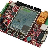
... PIC32-MAXI-WEB development board All boards produced by Olimex are RoHS compliant Copyright(c) 2011, OLIMEX Ltd, All rights reserved Users Manual Rev. A, February 2011 Page 1 ...
Page 2
... Three user buttons 3.3V voltage regulator Dimensions 140x100 mm (5.51x3.94") ELECTROSTATIC WARNING: The PIC32-MAXI-WEB board is shipped in protective anti-static packaging. The board must not be subject to high electrostatic potentials. General practice for working with static sensitive devices should be applied when working with this board. ...
Page 3
... Please note that the processor on this board is not supported by the once famous ICD2 programmer/debugger and derivatives, but by the PIC-KIT3 and other compatible tools. PIC32-MAXI-WEB is tested with MPLAB IDE v8.63 + MPLAB C32 v1.10B C compiler possible that the demo application may not work as expected as new releases of MPLAB and the C32 compiler are released in the future ...
Page 4
... MICROCONTROLLER FEATURES: PIC32-MAXI-WEB board use MCU PIC32MX795F512L from Microchip Technology with these features: High-Performance 32-bit RISC CPU: MIPS32 80 MHz maximum frequency 1.56 DMIPS/MHz (Dhrystone 2.1) performance at zero Wait state Flash access Single-cycle multiply and high-performance divide unit MIPS16e™ mode for up to 40% smaller code size ...
Page 5
Hardware Real-Time Clock and Calendar (RTCC) Five 16-bit Timers/Counters (two 16-bit pairs combine to create two 32-bit timers) Five Capture inputs Five Compare/PWM outputs Five external interrupt pins High-speed I/O pins capable of toggling MHz High-current ...
Page 6
BLOCK DIAGRAM: Page 6 ...
Page 7
MEMORY MAP: Page 7 ...
Page 8
... R70 10k 10k R71 R68 PMD14 PMD15 330R 330R R72 R69 3.3VA NA(100R) NA(100R) C36 C35 BUT1 BUT2 NA(100nF) NA(100nF) PIC32-MAXI-WEB AGND Rev. A COPYRIGHT(C) 2011, OLIMEX Ltd. http://www.olimex.com/dev R32 NA RXD1_INT R33 4.7k 3.3V R34 0R(NA) SW _SDA1 0R R35 NA AETXEN R36 NA MISO3A ...
Page 9
... LEDs on and working Ethernet connection. RESET CIRCUIT: PIC32-MAXI-WEB reset circuit is made of D4 (1N4148), RC group R55 – 10k and C31 – 100nF. Serial resistor R56 – 330Ω is used to prevent fast C31 charge and discharge when PIC32MX795F512L is being programmed. ...
Page 10
... JUMPER DESCRIPTION: 3.3V_E Enables 3.3V supply for PIC32MX795F512L and all other devices. Default state closed (shorted). 3.3VA_E Enables 3.3V positive supply for analog modules. Default state is closed (shorted). VDD_E Enables PIC32MX795F512L's 3.3V power supply. Default state is closed (shorted). AGND_E Enables the analog ground. ...
Page 11
... Reset button with name RESET – connected to PIC32MX460F512L pin 13 (#MCLR). One analog trimmer with name AN_TR – connected to PIC32MX795F512L pin 32 (AN8/C1OUT/RB8). Status Led (yellow) with name LED1 – connected to PIC32MX795F512L pin 34 (AN10/CVREFOUT/PMA13/RB10). Status Led (green) with name LED2 – connected to PIC32MX795F512L pin 76 (OC2/RD1). Status Led (red) with name LED3 – ...
Page 12
EXTERNAL CONNECTOR DESCRIPTION: ICSP: PGED2 I/O Program Data. Serial data for programming. PGEC2 Input Program Clock. Clock used for transferring the serial data (output from ICSP, input for the MCU). RS232: Pin # ...
Page 13
LAN: Pin # Signal Name Chip Side 1 TX+ 2 TX- 3 VCC/2 (2.5V) 4 Not Connected (NC) LED Color Left Yellow Right Green REL: Pin # 1 Normal Open 2 Common 3 Normal Close 4 Normal Open 5 Common ...
Page 14
CAN1: Pin # CAN2: Pin # JTAG: Pin # Signal GND CANL CANH Signal GND CANL CANH Signal Name NC ...
Page 15
PWR_JACK: Pin # Signal Name 1 Power Input 2 USB_OTG Pin # Signal Name 1 +5V_VBUS 2 USB_D- 3 USB_D+ 4 USBID 5 GND UEXT1: Pin # Signal Name 1 3 GND 3 TXD1 4 RXD1 5 SCL1 ...
Page 16
UEXT2: Pin # Signal Name 3 GND 3 U2TX 4 U2RX 5 SCL2 6 SDA2 7 MISO3A 8 MOSI3A 9 AC1TX/SCK3A 10 UEXT2_CS SD/MMC: Pin # Signal Name 1 MCIDAT2 2 CS_MMC 3 MOSI3A 4 VDD (3.3 ...
Page 17
MECHANICAL DIMENSIONS: Page 17 ...
Page 18
... AVAILABLE DEMO SOFTWARE: You could find demo software for PIC32-MAXI-WEB board on www.olimex.com/dev - DemoSoft PIC32-MAXI-WEB v.1.00 Description: The demo demonstrates the functionality of the various peripherals of the board including user input, serial communication, Graphical User Interface (GUI) and Network connectivity The demo is built upon the following Microchip's freely distributed support libraries: - Microchip Graphics Library v2 ...
Page 19
MPLAB IDE v8.50 MPLAB C32 v1.10B Microchip Graphics Library v2.00 FreeRTOS v6.0.2 Debugger used: PICKit3 by Microchip Page 19 ...
Page 20
... ORDER CODE: PIC32-MAXI-WEB – assembled and tested (no kit, no soldering required) How to order? You can order to us directly or by any of our distributors. Check our web Revision history: Rev. A www.olimex.com/dev for more info. - created February 2011 Page 20 ...
Page 21
... However all warranties implied or expressed including but not limited to implied warranties of merchantability or fitness for purpose are excluded. This document is intended only to assist the reader in the use of the product. OLIMEX Ltd. shall not be liable for any loss or damage arising from the use of any information in this document or any error or omission in such information or any incorrect use of the product ...