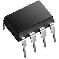
XRP7665EVB Exar Corporation, XRP7665EVB Datasheet - Page 8

XRP7665EVB
Manufacturer Part Number
XRP7665EVB
Description
Power Management Modules & Development Tools Eval Board for XRP7665 Series
Manufacturer
Exar Corporation
Type
PMIC Solutionsr
Datasheet
1.XRP7665EVB.pdf
(12 pages)
Specifications of XRP7665EVB
Maximum Operating Temperature
+ 85 C
Operating Supply Voltage
4.75 V to 18 V
Product
Power Management Development Tools
For Use With/related Products
XRP7665
Lead Free Status / RoHS Status
Lead free / RoHS Compliant
Where:
ΔI
nominally set to 30%-40% of I
f
As an example, inductor values for several
common output voltages are shown in tables 1
and 2. Note that example inductors shown in
tables 1 and 2 are Wurth shielded inductors. If
the target application is not sensitive to EMI
then unshielded inductors may be used.
OUTPUT CAPACITOR C
Select the output capacitor for voltage rating,
capacitance
Resistance ESR. The voltage rating, as a rule
of thumb, should be at least twice the output
voltage.
capacitance,
requirement is current load-step transient. If
the
transitions from a high to a low current) is
met, then usually the loading transient (when
load transitions from a low to a high current)
is met as well. Therefore calculate the C
© 2011 Exar Corporation
VOUT(V) ΔI
VOUT(V) ΔI
S
L
is nominal switching frequency (340kHz)
Table 1: Suggested inductor values for V
5.0
3.3
2.5
1.8
1.5
1.2
3.3
2.5
1.8
1.5
1.2
Table 2: Suggested inductor values for V
is peak-to-peak inductor current ripple
unloading
When
L(p-p)
L(p-p)
0.9
0.7
0.6
0.6
0.5
0.6
0.7
0.8
0.7
0.6
0.5
C
(A)
(A)
OUT
usually
transient
calculating
I
I
OUT
OUT
and
L(µH)
L(µH)
OUT
=3A
=3A
7.6
7.6
4.9
4.9
4.9
4.9
4.9
4.9
10
10
10
Equivalent
(i.e.,
the
OUT
the
744314101
744314101
744314101
744314760
744314760
744314490
744314490
744314490
744314490
744314490
744314490
Inductor
Example
Inductor
Example
IN
when
IN
=12V and
=5V and
overriding
required
Series
3
3
load
A
A
OUT
1
1
8/12
8
8
V
V
based on the unloading transient requirement
from:
Where:
L is the inductance calculated in the preceding
step
I
unloading. This is nominally set equal to
regulator current rating (3A).
I
This is nominally set equal to 50% of regulator
current rating (1.5A).
V
transient
mentioned above. V
from 3% to 5% of V
ESR of the capacitor has to be selected such
that the output voltage ripple requirement
ΔV
ripple ΔV
components: the resistive ripple due to ESR
and capacitive ripple due to C
transfer. For applications requiring low voltage
ripple, ceramic capacitors are recommended
because of their low ESR which is typically in
the range of 5mΩ. Therefore ΔV
capacitive. For ceramic capacitors calculate
the ΔV
Where:
ΔI
C
f
If tantalum or electrolytic capacitors are used
then ΔV
INPUT CAPACITOR C
Select the input capacitor for voltage rating,
RMS current rating and capacitance. The
voltage rating should be at least 50% higher
than the regulator’s maximum input voltage.
Calculate the capacitor’s current rating from:
S
S
s
High
Low
transient
OUT
y
y
is nominal switching frequency (340kHz)
L
OUT
n
n
is from table 1 or 2
is the value of load-step after unloading.
is the value calculated above
c
c
, nominally 1% of V
is
h
h
OUT
OUT
r
r
is the maximum permissible voltage
o
o
the
from:
OUT
n
corresponding
n
is essentially a function of ESR:
o
o
u
u
value
is mainly composed of two
s
s
S
S
t
t
transient
OUT
IN
e
e
8
p
of
p
.
-
-
D
D
load-step
OUT
is typically specified
to
o
o
w
w
, is met. Voltage
the
n
n
X
X
C
C
OUT
R
R
o
o
OUT
load
P
n
P
n
is mainly
Rev. 1.0.0
prior
v
v
7
7
charge
e
e
6
6
r
r
step
6
t
6
t
e
e
5
to
5
r
r


