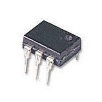
VO4158M Vishay, VO4158M Datasheet - Page 6

VO4158M
Manufacturer Part Number
VO4158M
Description
Triac & SCR Output Optocouplers Zero Crossing Photo Triac 800V 3mA
Manufacturer
Vishay
Datasheet
1.VO4158D.pdf
(8 pages)
Specifications of VO4158M
Isolation Voltage
5300 Vrms
Configuration
1
Maximum Continuous Output Current
300 mA
Maximum Input Current
60 mA
Maximum Operating Temperature
+ 100 C
Maximum Power Dissipation
600 mW
Maximum Reverse Diode Voltage
6 V
Minimum Operating Temperature
- 55 C
Output Type
AC
Package / Case
PDIP-6
Typical Input Voltage
1.2 V
Zero-crossing Circuit
Yes
Zero-crossing Voltage
20 V
Output Device
Triac
Peak Output Voltage (vdrm)
800 V
Maximum Input Voltage
1.4 V
Maximum Output Voltage
560 VAC
Minimum Trigger Current
3 mA (Max)
No. Of Channels
1
Optocoupler Output Type
Phototriac
Input Current
10mA
Output Voltage
800V
Opto Case Style
DIP
No. Of Pins
6
Input Current Max
10mA
Forward Voltage
1.2V
Rohs Compliant
Yes
Lead Free Status / RoHS Status
Lead free / RoHS Compliant
VO4157, VO4158
Vishay Semiconductors
www.vishay.com
952
21613
20005
21614
Fig. 12 - Basic Power Triac Driver Circuit
18
16
14
12
10
3.5
3.0
2.5
2.0
1.5
1.0
0.5
0.0
Fig. 11 - I
8
6
4
2
0
10
0
Fig. 10 - I
- 40 ºC
50
20
85 °C
FT
50 °C
Trigger Pulse Width (µs)
25 ºC
vs. V
FT
100 150 200 250
85 ºC
30
vs. LED Pulse Width
RMS
V
RMS
For technical questions, please contact: optocoupler.answers@vishay.com
40
100 °C
and Temperature
100 ºC
(V)
25 °C
50
Optocoupler, Phototriac Output,
Zero Crossing, High dV/dt, Low
60
300 350
70
Input Current
POWER FACTOR CONSIDERATIONS
As a zero voltage crossing optotriac, the commutating dV/dt
spikes can inhibit one half of the TRIAC from turning on. If the
spike potential exceeds the inhibit voltage of the zero-cross
detection circuit, half of the TRIAC will be held-off and not
turn-on. This hold-off condition can be eliminated by using a
capacitor or RC snubber placed directly across the power
triac as shown in figure 11. Note that the value of the
capacitor increases as a function of the load current.
The hold-off condition also can be eliminated by providing a
higher level of LED drive current. The higher LED drive
provides
phototransistor to turn-on before the commutating spike has
activated the zero-cross detection circuit. For example, if a
device requires 1.5 mA for a resistive load, then 2.7 mA
(1.8 times) may be required to control an inductive load
whose power factor is less than 0.3.
a
larger
photocurrent
Document Number: 84634
which
Rev. 1.5, 03-Nov-08
causes
the


