K817P8 Vishay, K817P8 Datasheet
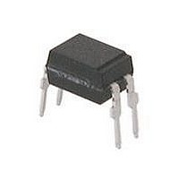
Transistor Output Optocouplers Phototransistor Out Single CTR 130-260%

K817P8

Manufacturer Part Number
K817P8
Description
Transistor Output Optocouplers Phototransistor Out Single CTR 130-260%
Manufacturer
Vishay
Datasheet

Specifications of K817P8

Isolation Voltage
5000 Vrms
Maximum Input Diode Current
60 mA
Maximum Reverse Diode Voltage
6 V
Output Device
Phototransistor
Output Type
DC
Configuration
1 Channel
Input Type
DC
Maximum Collector Emitter Voltage
70 V
Maximum Collector Emitter Saturation Voltage
0.3 V
Current Transfer Ratio
260 %
Maximum Forward Diode Voltage
1.6 V
Maximum Collector Current
50 mA
Maximum Power Dissipation
200 mW
Maximum Operating Temperature
+ 100 C
Minimum Operating Temperature
- 40 C
Package / Case
PDIP-4
No. Of Channels
1
Optocoupler Output Type
Phototransistor
Input Current
50mA
Output Voltage
70V
Opto Case Style
DIP
No. Of Pins
4
Mounting Type
Through Hole
Lead Free Status / RoHS Status
Lead free / RoHS Compliant

Available stocks

Company
Part Number
Manufacturer
Quantity
Price
Part Number:
K817P8
Manufacturer:
VISHAY/威世
Quantity:
20 000
DESCRIPTION
In the K817P part each channel consists of a phototransistor
optically coupled to a gallium arsenide infrared-emitting
diode in a 4 pin (single) plastic dual inline package.
AGENCY APPROVALS
• UL1577, file no. E52744, double protection
• cUL CSA 22.2 bulletin 5A, double protection, E52744
Document Number: 83522
Rev. 1.9, 14-Oct-09
ORDER INFORMATION
PART
K817P
K817P1
K817P2
K817P3
K817P4
K817P5
K817P6
K817P7
K817P8
K817P9
ABSOLUTE MAXIMUM RATINGS
PARAMETER
INPUT
Reverse voltage
Forward current
Forward surge current
Power dissipation
Junction temperature
OUTPUT
Collector emitter voltage
Emitter collector voltage
Collector current
Collector peak current
Power dissipation
Junction temperature
17918_13
Optocoupler, Phototransistor Output
For technical questions, contact:
17203-5
C
t
p
TEST CONDITION
C
A
1
/T = 0.5, t
(1)
t
E
C
p
≤ 10 µs
p
≤ 10 ms
optocoupleranswers@vishay.com
FEATURES
• Endstackable to 2.54 mm (0.1") spacing
• DC isolation test voltage 5000 V
• Current transfer ratio (CTR) selected into
• Low temperature coefficient of CTR
• Wide ambient temperature range
• Available in single, dual and quad channel packages
• Compliant to RoHS directive 2002/95/EC and in
APPLICATIONS
• Programmable logic controllers
• Modems
• Answering machines
• General applications
groups
accordance to WEEE 2002/96/EC
SYMBOL
V
V
P
P
I
I
FSM
V
CEO
ECO
T
I
CM
T
I
diss
diss
F
C
R
j
j
CTR 100 % to 200 %, DIP-4
CTR 160 % to 320 %, DIP-4
CTR 100 % to 300 %, DIP-4
CTR 130 % to 260 %, DIP-4
CTR 200 % to 400 %, DIP-4
CTR 50 % to 600 %, DIP-4
CTR 63 % to 125 %, DIP-4
CTR 50 % to 150 %, DIP-4
CTR 80 % to 160 %, DIP-4
CTR 40 % to 80 %, DIP-4
Vishay Semiconductors
REMARKS
VALUE
125
100
125
1.5
60
70
70
50
70
6
7
RMS
www.vishay.com
K817P
UNIT
mW
mW
mA
mA
mA
°C
°C
V
A
V
V
1

Related parts for K817P8

K817P8 Summary of contents

Page 1

... CSA 22.2 bulletin 5A, double protection, E52744 ORDER INFORMATION PART K817P K817P1 K817P2 K817P3 K817P4 K817P5 K817P6 K817P7 K817P8 K817P9 ABSOLUTE MAXIMUM RATINGS PARAMETER INPUT Reverse voltage Forward current Forward surge current Power dissipation Junction temperature OUTPUT Collector emitter voltage ...

Page 2

... MHz C k TEST CONDITION PART = K817P CE F K817P1 K817P2 = K817P3 K817P4 K817P5 K817P6 = K817P7 CE F K817P8 K817P9 optocoupleranswers@vishay.com VALUE 5000 ISO P 200 tot - 100 amb 125 stg T 260 sld MIN. TYP. MAX. 1.25 1 100 0.3 100 0.6 SYMBOL MIN. ...

Page 3

... off (see figure mA kΩ (see figure mA kΩ off (see figure 2) input amplitude Oscilloscope MΩ Oscilloscope ≥ MΩ L ≤ optocoupleranswers@vishay.com Vishay Semiconductors MIN. TYP. MAX 4.7 0 100 % off on t Pulse duration t Storage time Delay time ...

Page 4

... K817P Vishay Semiconductors TYPICAL CHARACTERISTICS °C, unless otherwise specified amb 300 Coupled device 250 200 Phototransistor 150 IR-diode 100 Ambient Temperature (°C) 96 11700 amb Fig Total Power Dissipation vs. Ambient Temperature 1000 100 10 1 0.1 0 0.4 0.8 1 Forward Voltage (V) 96 11862 F Fig Forward Current vs. Forward Voltage 2 ...

Page 5

... I - Forward Current (mA) 95 11031 F Fig Turn-on/Turn-off Time vs. Forward Current Document Number: 83522 For technical questions, contact: Rev. 1.9, 14-Oct-09 Optocoupler, Phototransistor Output 20 % used 100 100 10 t off optocoupleranswers@vishay.com Vishay Semiconductors 10 Non-saturated operation 100 Ω off Collector Current (mA) 95 11030 C Fig Turn-on/off Time vs. Collector Current www ...

Page 6

... K817P Vishay Semiconductors PACKAGE DIMENSIONS in millimeters 6.5 ± 0.3 Pin 1 identifier i178027-4 PACKAGE MARKING www.vishay.com For technical questions, contact: 6 Optocoupler, Phototransistor Output 4.58 ± 0.3 0.4 ± 0.1 3.5 ± 0.1 4.5 ± 0.3 1.3 ± 0.1 0.5 ± 0.1 2.54 typ. ...

Page 7

... Vishay disclaims any and all liability arising out of the use or application of any product described herein or of any information provided herein to the maximum extent permitted by law. The product specifications do not expand or otherwise modify Vishay’ ...

Related keywords