1761889-1 TE Connectivity, 1761889-1 Datasheet - Page 7
1761889-1
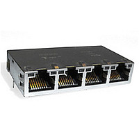
Manufacturer Part Number
1761889-1
Description
Manufacturer
TE Connectivity
Type
RJ-45r
Datasheet
1.1761889-1.pdf
(8 pages)
Specifications of 1761889-1
Positions Loaded
48
Number Of Contacts
48POS
Body Orientation
Right Angle
Pitch (mm)
2.03mm
Contact Material
Phosphor Bronze
Operating Temp Range
0C to 70C
Housing Color
Black
Number Of Ports
4Port
Gender
F
Mounting Style
Through Hole
Contact Plating
Gold Over Nickel
Housing Material
Polybutylene Terepht
Product Type
Connector
Number Of Cores
12
Magnetics
Integrated Magnetics
Jack Type
RJ45
Signal Routing Type
Auto MDI/MDIX
Profile
Low
Pcb Mounting Orientation
Side Entry (Right Angle)
Jack Configuration
1 x 4
Turns Ratio
1:1
Shielded
Yes
Emi Finger - Bottom
Without
Termination Method
Solder
Port Configuration
Multiple
Emi Fingers -top And Sides
With
Latch Orientation
Inverted - Latch Up
Pcb Tail Length (mm [in])
2.74 [0.108]
Contact Termination Type
Through Hole
Preloaded
Yes
Connector Style
Jack
Status Indicator
LED
Decoupling Capacitor
2KV
Rear Pcb Ground Tab
Without
Signal Lead Quantity
12
Rohs/elv Compliance
RoHS compliant, ELV compliant
Lead Free Solder Processes
Wave solder capable to 240°C, Wave solder capable to 260°C, Wave solder capable to 265°C
Rohs/elv Compliance History
Always was RoHS compliant
Left Led Color (position #1)
Green
Right Led Color (position #2)
Green
Operating Temperature (°c [°f])
0 – 70 [32 – 158]
Applies To
Printed Circuit Board
Environmental Conditions
Office / Premises
Application
Gigabit Ethernet
Lead Free Status / RoHS Status
Compliant


30
MAG45 with PoE Controller
RJ45 + PoE Magnetics +
Silicon Power Controller
Chip
PoE Product Features
■
■
■
■
■
Customer Benefits:
■
■
■
■
Why Integrate the PoE
Circuitry into the RJ?
■
■
■
■
■
Catalog 82066
Revised 11-07
www.tycoelectronics.com
Integrated Silicon PoE
12-port controller
■
■
Footprint
■
■
Pin Assignments
■
Three options in same
footprint:
■
■
■
2250Vdc / 1500Vac
electrical isolation per
802.3 requirements
Simplify implementation of
full PoE solution
Board real estate savings
Reduce board layout issues
Integrate new and existing
technologies into a single
connector unit
Single package (PoE, LED’s,
Magnetics, Heat Sink)
Identical footprint for both
Integrated PoE/Enabled and
non-PoE
Single design, single
motherboard can be used
for both PoE and non-PoE
Same design can migrate
between switches (including
blades and fixed)
Delivered fully tested and
qualified, no need to bother
with complicated PoE
testing
802.3af compliant
Auto and Enhanced mode
capable
Press-fit configuration
Ease of routing on
customer PCB
Signal integrity benefits
vs. standard footprint
Integrated Magnetics Only
Integrated Magnetics,
Enabled PoE
Integrated Magnetics,
Integrated PoE
are metric equivalents.
Dimensions are in inches and
millimeters unless otherwise
specified. Values in brackets
Modular Jacks and MRJ21 Product
MAG45 Modular Jacks with Integrated Magnetics
■
■
■
■
■
■
PoE Controller Features
■
■
■
■
Reduced layer count/
Reduces cost of motherboard
No PoE daughterboards
Isolated PoE voltage
provided directly from the
power supply
All per port components
embedded in RJ
Eliminates issues of voltage
isolation on motherboard
Reduces EMI risks
Power supplied over data
contacts 1 & 2 and 3 & 6
I2C Capability
PoE chip provides power
and command/control
circuitry from motherboard
power plane/bus
Provides isolation between
earth/building and signal
ground
Legacy Footprint
Dimensions are shown for
reference purposes only.
Specifications subject
to change.
Solder Only
Legacy vs. Press Fit PoE Footprint
■
■
■
■
■
■
■
How Does PoE RJ45 Work?
■
■
Real time control of
overload, underload, short
circuits and under voltage
states
0.5A current carrying
capacity
Full AC disconnect and
classification
80V tolerant, surge
protected system
Registers for MIB 8 support
and parameters adjustment
Single voltage feeding
(44 – 57VDC)
Designed to support legacy
capacitor detection
Embedded inside each
RJ45 is the Silicon Power
PD64012 chip
Each RJ45 is a 12 port PoE
system, communicating
USA: 1-800-522-6752
Canada: 1-905-470-4425
Mexico: 01-800-733-8926
C. America: 52-55-1106-0803
Integrated/Enabled/Non PoE Footprint
(Continued)
■
■
For assistance in part selec-
tion, please refer to the
Tyco Electronics
E-Catalog.
Your Tyco Electronics Sales
Representative or one of the
Product Information Centers
listed below are also avail-
able to assist.
with each other to create a
system of up to 48 ports
The Host CPU controls the
system via I2C
Two main operating modes:
Automatic/Enhanced Mode
to match system customiza-
tion requirements
Press Fit
South America: 55-11-2103-6000
Hong Kong: 852-2735-1628
Japan: 81-44-844-8013
UK: 44-8706-080-208
Related parts for 1761889-1
Image
Part Number
Description
Manufacturer
Datasheet
Request
R

Part Number:
Description:
Printers THERMAL PRINTER HS-SLEEVE MARKER
Manufacturer:
TE Connectivity


Part Number:
Description:
High Speed / Modular Connectors 30P HEADER ASSY
Manufacturer:
TE Connectivity
Datasheet:

Part Number:
Description:
High Speed / Modular Connectors REC 6X005P R/A LT B-PLANE HS3
Manufacturer:
TE Connectivity
Datasheet:

Part Number:
Description:
High Speed / Modular Connectors 2MM HM RCPT 50P R/A AU
Manufacturer:
TE Connectivity
Datasheet:

Part Number:
Description:
High Speed / Modular Connectors 2MM HM RCPT 50P R/A AU
Manufacturer:
TE Connectivity
Datasheet:


Part Number:
Description:
Manufacturer:
TE Connectivity
Datasheet:


Part Number:
Description:
Manufacturer:
TE Connectivity
Datasheet:

Part Number:
Description:
Manufacturer:
TE Connectivity
Datasheet:

Part Number:
Description:
Manufacturer:
TE Connectivity
Datasheet: