211758-1 TE Connectivity, 211758-1 Datasheet - Page 10
211758-1
Manufacturer Part Number
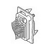
211758-1
Description
PLUG & SOCKET HOUSING, PLUG, PLASTIC
Manufacturer
TE Connectivity
Type
Housingr
Series
Metrimater
Datasheet
1.211758-1.pdf
(64 pages)
Specifications of 211758-1
Number Of Contacts
12POS
Number Of Contact Rows
4
Body Orientation
Straight
Pitch (mm)
5.08mm
Gender
PL
Housing Material
Thermoplastic
Operating Temp Range
-55C to 130C
Current Rating (max)
14/ContactA
Voltage Rating Max
600VAC
Housing Color
Black
Product Height (mm)
38.1mm
Product Depth (mm)
30.23mm
Product Length (mm)
49.33mm
No. Of Positions
12
Pitch Spacing
5.08mm
Connector Mounting
Panel
Mounting Type
Panel
Color
Black
Rohs Compliant
Yes
Product Type
Housing
Connector Type
Housing
Keyed
No
Mount
Panel
Mounting Ears
Without
Mating Connector Lock
Without
Pcb Mount Retention
Without
Voltage (vac)
600
Connector Configuration
Drawer
Drawer Style
Standard
Number Of Positions
12
Coaxial Socket
Without
Centerline (mm [in])
5.08 [0.200]
8/32 Insert
No
Ul Flammability Rating
UL 94V-0
Rohs/elv Compliance
RoHS compliant, ELV compliant
Lead Free Solder Processes
Wave solder capable to 240°C, Wave solder capable to 260°C, Wave solder capable to 265°C
Rohs/elv Compliance History
Always was RoHS compliant
Lead Free Status / RoHS Status
Compliant
For Use With
Metrimate Drawer Connectors
Available stocks
Company
Part Number
Manufacturer
Quantity
Price
Company:

Part Number:
211758-1
Manufacturer:
TE
Quantity:
20 000
Company:
Part Number:
211758-1
Manufacturer:
TE
Quantity:
35 000


10
Type III+, Crimp, Snap-In
Contact Size - 16
Pin Diameter - 1.57 [.062]
Material and Finish
Contact Body - Copper alloy,
plated tin or gold
Spring - Stainless steel
Type III+ (Precision
Formed, Solder)
Contact Size - 16
Pin Diameter - .062 [1.57]
Material and Finish
Contact Body - Copper alloy,
plated tin to gold
Spring - Stainless steel
Related Product Data
Performance Characteristics -
Page 6
Technical Documents -
Page 80
Catalog 82045
Revised 06-08
www.tycoelectronics.com
1
2
3
*Commercial PRO-CRIMPER II hand tool for field repair only. Note: Die Set can be adapted for use with the 626 Pneumatic Tool System.
***Call Technical Support for Automatic Machine Applicator Part Numbers.
Extraction Tool Part No. 725840-1
Overall insulation crimp diameter, including crimp barrel, must not exceed 3.18 [.125].
Gold flash over 0.00076 [.000030] min. nickel on entire contact, with 0.00076 [.000030] gold in contact area.
To use with the 626 Pneumatic Tool System: remove the crimping head from the Straight Action Hand Tool (SAHT) Assembly, order SAHT Adapter
Part No. (Call Technical Support), Adapter Holder Part No. 356304-1 (with ratchet) or 189928-1 (without), and Power Unit Part No. 189721-1
(hand actuated) or 189722-1 (foot actuated).
0.12-0.2
0.2-0.6
Wire Size Range
[mm
0.8-1.4
2
]
24-20
26-24
AWG
18-16
Dimensions are in millimeters
and inches unless otherwise
specified. Values in brackets are
equivalent U.S. Customary Units.
.035-.055
.045-.070
.078-.098
1.98-2.49
0.89-1.4
1.14-1.78
Range
Dia.
Ins.
AMP Metrimate
Pin and Socket Connectors
Signal Contacts
1
Contact Size 16—Pin Diameter .062 [1.57] (Test Current, 13 Ampere)‡
1
2
3
4
Note: These contacts can be used in Multimate contact cavities of all connector housings.
‡Single contact, free-air test current is not to be construed as contact rating current. Use only for testing.
Extraction Tool Part No. 305183
.000030 [0.00076] gold in mating area over .000030 [0.00076] min. nickel.
Duplex plated .000030 [0.00076] gold in mating area over .000030 [0.00076] min. nickel on contact body; bright tin on
solder tab.
Bright tin on entire contact.
Designed for up to 14 AWG; but, not to exceed current limitation of contact.
Refer to contact current carrying capability information on page 8.
A W G
26-20
18-16
Grounding Pin
(make first - break last)
Related Product Data
Application Tooling -
Pages 56, 57
Technical Documents -
Page 58
Sel. Gold/Nickel
Sel. Gold/Nickel
Sel. Gold/Nickel
(with Preformed Wire Barrel/
Solder Tab
Wire Size
Bright Tin
R a n g e
Contact
Solder-Type
Finish
Insulation Support)
Solder-Tab
Tin
Tin
4
0.12-0.6
0.8-1.4
Dimensions are shown for
reference purposes only.
Specifications subject
to change.
m m
2
2
2
2
(Continued)
Strip Form
164160-3
164160-4
164159-3
164159-4
164161-3
164161-4
Grounding Pin Part No.
Gold/Nickel
Gold/Nickel
Bright Tin
USA: 1-800-522-6752
Canada: 1-905-470-4425
Mexico: 01-800-733-8926
C. America: 52-55-5-729-0425
Contact
Duplex
Finish
Loose Piece
NOTE: All part numbers
are RoHS Compliant
164162-2
164163-2
164164-2
164162-1
164163-1
164164-1
2
1
1
Pin
Pin
466323- ***
466907-2***
466741- ***
680114-3***
266182-1
266180-1
202236-7
202236-5
Strip Form
Applicator
Part No.
P i n
South America: 55-11-3611-1514
Hong Kong: 852-2735-1628
Japan: 81-44-844-8013
UK: 44-141-810-8967
—
Loose Piece
Contact No.
or
or
Socket
Socket
Loose Piece
91515-1
58495-1*
91515-1
91505-1
58495-1*
91523-1
91505-1
58495-1*
Hand Tool
266183-1
266181-1
202237-7
202237-5
Part No.
Socket
3
3
3
3
3
or
or
or
or
or
Related parts for 211758-1
Image
Part Number
Description
Manufacturer
Datasheet
Request
R


Part Number:
Description:
Printers THERMAL PRINTER HS-SLEEVE MARKER
Manufacturer:
TE Connectivity


Part Number:
Description:
High Speed / Modular Connectors 30P HEADER ASSY
Manufacturer:
TE Connectivity
Datasheet:

Part Number:
Description:
High Speed / Modular Connectors REC 6X005P R/A LT B-PLANE HS3
Manufacturer:
TE Connectivity
Datasheet:

Part Number:
Description:
High Speed / Modular Connectors 2MM HM RCPT 50P R/A AU
Manufacturer:
TE Connectivity
Datasheet:

Part Number:
Description:
High Speed / Modular Connectors 2MM HM RCPT 50P R/A AU
Manufacturer:
TE Connectivity
Datasheet:


Part Number:
Description:
Manufacturer:
TE Connectivity
Datasheet:


Part Number:
Description:
Manufacturer:
TE Connectivity
Datasheet:

Part Number:
Description:
Manufacturer:
TE Connectivity
Datasheet: