3-530655-3 TE Connectivity, 3-530655-3 Datasheet - Page 59
3-530655-3
Manufacturer Part Number
3-530655-3
Description
Manufacturer
TE Connectivity
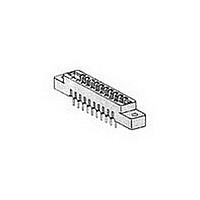
Type
Card Edger
Datasheet
1.3-530655-3.pdf
(96 pages)
Specifications of 3-530655-3
Number Of Contacts
86POS
Number Of Contact Rows
2
Body Orientation
Straight
Contact Plating
Gold Over Nickel
Contact Material
Phosphor Bronze
Termination Method
Solder
Mounting Style
Through Hole
Product Height (mm)
11.68mm
Pitch (mm)
3.96mm
Housing Material
Polyester
Housing Color
Green
Number Of Dual Positions
43
Post Type
Flow Solder Post
Mounting Ears
With
Mounting Ear Style
Without Threaded Inserts
Termination Post Length (mm [in])
3.81 [0.150]
Centerline (mm [in])
3.96 [0.156]
Row-to-row Spacing (mm [in])
5.08 [0.200]
Post Plating
Bright Tin (100)
Contact Base Material
Phosphor Bronze
Contact Plating, Mating Area, Material
Gold (30)
Underplate Material
Nickel
Rohs/elv Compliance
Not ELV/RoHS compliant
Lead Free Solder Processes
Wave solder capable to 240°C
Lead Free Status / RoHS Status
Not Compliant


[8.51]
.335
Typ.
Catalog 1654080
Issued 7-03
www.tycoelectronics.com
Material and Finish:
Housing—Green, glass-filled
polyester
Contacts—Phosphor bronze, duplex
plated .000030 [0.00076] gold in con-
tact area; .000100 [0.00254] bright tin
on posts, with entire contact under-
plated .000030 [0.00076] nickel
Related Product Data:
Keying Plug—page 63
PC Board Hole Layouts—See below
PC Board Edge Pattern—page 63
Technical Documents:
(pages 186, 187):
Product Specification
108-9044
Instruction Sheet 408-7772
[7.49]
[4.19]
.295
.165
.200 [5.08] Row-to-Row Spacing
[3.25]
.128
Post Length
(See Chart)
Flow Solder Post
[3.18]
. 1 2 5
PC Board Hole Layout
Dia.
Recommended
R e f .
[5.08]
.200
B
[3.18]
.125
Dimensions are in inches and
millimeters unless otherwise
specified. Values in brackets
are metric equivalents.
[1.32]
.052
Dia.
[2.54]
.100
Card Edge Connectors
(Solder Type, Board-to-Board)
Low Profile Connectors, .125 [3.18] Centerline
[5.08]
.200
[8.51]
.335
Typ.
[4.19]
[7.49]
.165
.295
.140 [3.56] Row-to-Row Spacing
Dimensions are shown for
reference purposes only.
Specifications subject
to change.
#1 Cavity Identification
[3.25]
.128
[3.18]
PC Board Hole Layout
. 1 2 5
Post Length
(See Chart)
Flow Solder Post
Dia.
Recommended
[3.18]
.125
R e f .
PCBoard Thickness—
.055-.070 [1.40-1.78]
[3.18]
.125
B
Molded Characters (Upper and Lower Case
Letters Omitting Letters G, I, O &Q)
1
A
2
B
[3.56]
.140
[1.32]
.052
USA: 1-800-522-6752
Canada: 1-905-470-4425
Mexico: 01-800-733-8926
C. America: 52-55-5-729-0425
[3.18]
.125
[3.18]
C
.125
3
Dia.
B
D
[1.78]
A
E
.070
Typ.
Typ.
D
4
[3.56]
.140
5
E
F
6
[7.49]
[4.19]
.165
.295
2 (Plcs.)
[3.25]
.128
.235 [5.97] Row-to-Row Spacing
South America: 55-11-3611-1514
Hong Kong: 852-2735-1628
Japan: 81-44-844-8013
UK: 44-141-810-8967
Dia.
[3.18]
. 1 2 5
[3.81]
Solder Eyelet Contact
.150
[7.11]
.280
[6.35]
.250
[7.62]
.300
R e f .
[11.68]
.460
Ref.
C
[5.97]
.235
Ref.
59
Related parts for 3-530655-3
Image
Part Number
Description
Manufacturer
Datasheet
Request
R

Part Number:
Description:
CONN HDR BRKWAY 53/54POS DUAL
Manufacturer:
Tyco Electronics
Datasheet:

Part Number:
Description:
Manufacturer:
TE Connectivity
Datasheet:
Part Number:
Description:
Manufacturer:
TE Connectivity
Datasheet:
Part Number:
Description:
Manufacturer:
TE Connectivity
Datasheet:
Part Number:
Description:
Manufacturer:
TE Connectivity
Datasheet:

Part Number:
Description:
Manufacturer:
TE Connectivity
Datasheet:

Part Number:
Description:
Conn IDC Connector F 5 POS 2.54mm IDT RA Cable Mount Loose Piece
Manufacturer:
TE Connectivity
Datasheet:

Part Number:
Description:
Conn IDC Connector F 5 POS 2.54mm IDT RA Cable Mount Loose Piece
Manufacturer:
TE Connectivity
Datasheet:

Part Number:
Description:
Conn IDC Connector F 5 POS 3.96mm IDT RA Cable Mount
Manufacturer:
TE Connectivity
Datasheet:
Part Number:
Description:
Conn IDC Connector F 5 POS 3.96mm IDT RA Cable Mount
Manufacturer:
TE Connectivity
Datasheet:

Part Number:
Description:
Conn IDC Connector F 5 POS 2.54mm IDT RA Cable Mount Loose Piece
Manufacturer:
TE Connectivity
Datasheet:

Part Number:
Description:
Manufacturer:
TE Connectivity
Datasheet:
Part Number:
Description:
05P MTA100 CONN ASSY POL 15AU
Manufacturer:
TE Connectivity
Datasheet:

Part Number:
Description:
05P MTA156 POL HDR ASSY LF
Manufacturer:
TE Connectivity
Datasheet:

Part Number:
Description:
Manufacturer:
TE Connectivity
Datasheet: