SPT2AF-6PF20PPM Seiko Instruments, SPT2AF-6PF20PPM Datasheet
SPT2AF-6PF20PPM
Specifications of SPT2AF-6PF20PPM


Related parts for SPT2AF-6PF20PPM


SPT2AF-6PF20PPM Summary of contents
Page 1
... Seiko Instruments Inc strictly prohibited to copy all or part of these specifications to third parties without permission. 5. In the case that the products described herein are used as part of any devices or equipment which might influence any one of the human body, human life and property, such as physical exercise equipment, medical equipment or vehicles, please let us know that ...
Page 2
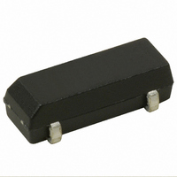
... These specifications apply to QUARTZ CRYSTAL RESONATORS ( hereinafter referred to as RESONATORS ) to be manufactured by Seiko Instruments Inc. ( hereinafter referred to as SII ) to 2.Designation RESONATORS are designated " SP-T2A-F"(32.768kHz ). 3.Shape and dimensions As per the SP-T2A-F drawing shown on page 5 . 4.Electrical characteristics Specified on page 2 through 3. ...
Page 3
Item 1 Storage temperature range 2 Maximum drive level [2] Recommended Operating Condition Item 1 Operating temperature range 2 Drive level [3] Electrical -Characteristics Item 1 Nominal frequency 2 Frequency tolerance 3 Load capacitance 4 Motional resistance 5 Q-value 6 Motional capacitance ...
Page 4
No Item 1 High temperature storage 2 Low temperature storage 3 High temperature and high humidity storage 4 Thermal shock resistance 5 Mechanical shock resistance 6 Vibration resistance 7 IR Reflow Note: 1. The adove tests no must be conducted independently (not ...
Page 5
Recommended mounting conditions Reflow profile Manual soldering (2) Cleaning The crystal resonator may be destroyed by ultrasonic cleaning. We don't guarantee the quality of the product with that cleaning method because such conditions as type of the washing machine, ...
Page 6
Out Line Drawing 1.Mechanical dimensions #4 #4 #4 #4 #4 #4 #4 #4 C2K60 #1 #1 #1 #1 #1 #1 #1 #1 8.7max. 8.7max. 8.7max. 8.7max. 8.7max. 8.7max. 8.7max. 8.7max. 0.5 3.Lead connection Do not connect Terminals #2, #3 ...
Page 7
Carrier tape see Drawing No. 8/11 ② Reel for carrier tape see Drawing No. 9/11 ① Carrier tape : Polystyrene ② Reel for carrier tape : HIPS (1) Taping shall be placed in tapes in such manner as to ...
Page 8
Gap between Carrier Tape and Cover Tape ①Cover Tape protrudes from Carrier Tape by 0.5mm max. Fig. 3 ② Holes of Carrier Tape are covered with Cover Tape by 0.75mm max. Fig. 4 (5) Peel strength ①The method of ...
Page 9
Carrier tape (1) Conforms with EIA-481 (2) Tolerance ± 0.2 4.0±0.1 4.0±0.1 4.0±0.1 4.0±0.1 +0.1 +0.1 +0.1 +0.1 φ1.5 φ1.5 φ1.5 φ1 8.0±0.1 8.0±0.1 8.0±0.1 8.0±0.1 3.9±0.1 3.9±0.1 3.9±0.1 3.9±0.1 B ...
Page 10
Conforms with EIAJ ET-7200B (2) Quantity per reel : 3,000pcs./ for a reel area A in detail area A in detail Taping reel :Label is pasted up on this area :Labeling area Unit : mm Unit : mm ...
Page 11
Profile ℃ ℃ +170±10 ℃ Note: The temperature used herein means the temperature on the circuit board. Reflow : 2 times max. +260 ℃ peak. +260 ℃ peak. +260 ℃ peak. +260 ℃ peak. +260 ℃ peak. +260 ℃ peak. ...
Page 12
Outside box packing specification 〔1〕 To attach the label every 1 volume of reel. 〔2〕 To insert it in the corner bottom Polyethylene bag. Label Label 【 Figure 1】 〔3〕 Box size and reels Outside Box Maximum reels 〔4〕 ...