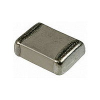
LLL31MR71H154MA01L Murata, LLL31MR71H154MA01L Datasheet - Page 160

LLL31MR71H154MA01L
Manufacturer Part Number
LLL31MR71H154MA01L
Description
Manufacturer
Murata
Datasheet
1.LLL31MR71H154MA01L.pdf
(220 pages)
Specifications of LLL31MR71H154MA01L
Tolerance (+ Or -)
20%
Voltage
50VDC
Temp Coeff (dielectric)
X7R
Operating Temp Range
-55C to 125C
Mounting Style
Surface Mount
Construction
SMT Chip
Case Style
Ceramic Chip
Failure Rate
Not Required
Wire Form
Not Required
Product Length (mm)
1.6mm
Product Depth (mm)
3.2mm
Product Height (mm)
1.15mm
Product Diameter (mm)
Not Requiredmm
Capacitance
.15uF
Package / Case
0612
Lead Free Status / RoHS Status
Compliant
- Current page: 160 of 220
- Download datasheet (4Mb)
8
!Note
• This PDF catalog is downloaded from the website of Murata Manufacturing co., ltd. Therefore, it’s specifications are subject to change or our products in it may be discontinued without advance notice. Please check with our
• This PDF catalog has only typical specifications because there is no space for detailed specifications. Therefore, please approve our product specifications or transact the approval sheet for product specifications before ordering.
sales representatives or product engineers before ordering.
!Note
1. Transportation
158
Notice
Notice
Others
1. The performance of a capacitor may be affected by the
conditions during transportation.
1-1. The capacitors shall be protected against
• Please read rating and !CAUTION (for storage, operating, rating, soldering, mounting and handling) in this catalog to prevent smoking and/or burning, etc.
• This catalog has only typical specifications because there is no space for detailed specifications. Therefore, please approve our product specifications or transact the approval sheet for product specifications before ordering.
excessive temperature, humidity and mechanical
force during transportation.
(1) Climatic condition
(2) Mechanical condition
• low air temperature: -40 C
• change of temperature air/air: -25 C/+25 C
• low air pressure: 30 kPa
• change of air pressure: 6 kPa/min.
Transportation shall be done in such a way that
the boxes are not deformed and forces are not
directly passed on to the inner packaging.
1-2. Do not apply excessive vibration, shock, and
1-3. Do not use a capacitor to which excessive shock
pressure to the capacitor.
(1) When excessive mechanical shock or pressure
(2) When a sharp edge of an air driver, a soldering
was applied by dropping, etc.
The capacitor dropped accidentally during
processing may be damaged.
is applied to a capacitor, chipping or cracking
may occur in the ceramic body of the capacitor.
iron, tweezers, a chassis, etc. impacts strongly
on the surface of capacitor, the capacitor may
crack and short-circuit.
C02E.pdf
09.9.18
Related parts for LLL31MR71H154MA01L
Image
Part Number
Description
Manufacturer
Datasheet
Request
R

Part Number:
Description:
Murata Microblower 20x20 DCDC Driver Board - Samples Only
Manufacturer:
Murata

Part Number:
Description:
357-036-542-201 CARDEDGE 36POS DL .156 BLK LOPRO
Manufacturer:
Murata
Datasheet:

Part Number:
Description:
Manufacturer:
Murata
Datasheet:

Part Number:
Description:
Manufacturer:
Murata
Datasheet:

Part Number:
Description:
Manufacturer:
Murata
Datasheet:

Part Number:
Description:
Manufacturer:
Murata
Datasheet:

Part Number:
Description:
Manufacturer:
Murata
Datasheet:

Part Number:
Description:
Manufacturer:
Murata
Datasheet:

Part Number:
Description:
Manufacturer:
Murata
Datasheet:

Part Number:
Description:
BLM21BD751SN1On-Board Type (DC) EMI Suppression Filters
Manufacturer:
Murata
Datasheet:

Part Number:
Description:
BLM15AG100SN1On-Board Type (DC) EMI Suppression Filters
Manufacturer:
Murata
Datasheet:

Part Number:
Description:
NFE31PT222Z1E9On-Board Type (DC) EMI Suppression Filters
Manufacturer:
Murata
Datasheet:

Part Number:
Description:
Chip Coil
Manufacturer:
Murata
Datasheet:

Part Number:
Description:
Chip Coil
Manufacturer:
Murata
Datasheet:


