SR211C103KAATR1 AVX Corporation, SR211C103KAATR1 Datasheet - Page 7
SR211C103KAATR1
Manufacturer Part Number
SR211C103KAATR1
Description
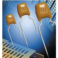
CAPACITOR CERAMIC, 0.01UF, 100V, X7R, Radial
Manufacturer
AVX Corporation
Series
SkyCapr
Datasheet
1.SR211C103KAATR1.pdf
(8 pages)
Specifications of SR211C103KAATR1
Tolerance (+ Or -)
10%
Voltage
100VDC
Temp Coeff (dielectric)
X7R
Operating Temp Range
-55C to 125C
Mounting Style
Through Hole
Construction
Radial
Case Style
Dipped
Failure Rate
Not Required
Wire Form
Inside Crmp Stndoff
Product Length (mm)
5.08mm
Product Depth (mm)
3.175mm
Product Height (mm)
5.08mm
Product Diameter (mm)
Not Requiredmm
Capacitance
.01uF
Package / Case
Not Required
Dielectric Characteristic
X7R
Capacitance Tolerance
± 10%
Voltage Rating
100VDC
Capacitor Case Style
Radial Leaded
No. Of Pins
2
Rohs Compliant
No
Lead Free Status / RoHS Status
Not Compliant
Available stocks
Company
Part Number
Manufacturer
Quantity
Price
Company:

Part Number:
SR211C103KAATR1-LF
Manufacturer:
AVX/PB
Quantity:
6 000
Company:
Part Number:
SR211C103KAATR1-LF
Manufacturer:
UNIT
Quantity:
6 000


Radial Leads/Packaging
Tape and Reel
GENERAL INFORMATION
1. Standard reel diameter is 355 millimeters (14 inches) maximum.
2. Reeling standard (#1 or #2) should be specified when ordering.
HOW TO ORDER
To specify tape and reel packaging, add TR1, TR2 or TRX to the
end of the AVX 12 digit part number.
Examples:
SR215C104KAATR1
SR305E105MAATR2
SR215C103JAATRX
L
32 max.
16±.5
32 max.
19 min.
SR29
A
SR29
SR28
K
E
T
SR28
B
SR12
O
SR12
SR21
D
SR21
SR13
N
C
M
Q
SR13
SR32
W
X
S
SR32
MR05
STANDARD 1
STANDARD 2
MR05
S
20
+1.5
-1.0
R
F
32 max.
(TRX)
SR21
19 min.
DESCRIPTION
A. Feed Hole Pitch
B. Feed Hole Diameter
C. Feed Hole Location
D. Component Lead Spacing
E. Component Lead Location
F. Component Lead Protrusion
K. Component Body Location
L. Carrier Tape Width
M. Carrier Tape Assembly Thickness
N. Carrier Tape Spliced Thickness
O. Carrier Tape Spliced Length
Q. Adhesive Tape Border
R. Component Bent Leads (either direction)
S. Component Misalignment
T. Component Pitch
W. Adhesive Tape Width
X. Carrier Tape Thickness
Y. Cumulative Pitch over 20 Pitches
SR32
(TRX)
(edge of carrier to cut end of lead)
SR63
(TRX)
SR15
SR20
THE INSERTABLES
32 mm max.
32 mm max.
32 max.
MR06
16 min.
16 ± 0.5 mm
19 mm min. to
base of unit
SR30
SR15
SR20
SR07
SR07
STANDARD 1
STANDARD 2
Dimensions in Millimeters
SR40
SR29
SR29
MR06
Dimensions in Millimeters
DIMENSIONS (MM)
SR59
SR59
SR30
3.81 ±.51 or 5.00 ±.51
5.00 +.79 or 2.54 +.79
for 2.54 lead spacing
2.00 maximum
1.42 maximum
3.00 maximum
5.00 minimum
.79 maximum
.99 maximum
SR65
50.80 - 88.90
SR65
-.20
18.01 +1.02
SR40
12.70 ± .20
12.70 ±.99
3.99 ± .20
9.02 ± .51
254 ±2.00
6.35 ±.41
.71 ± .20
.51 ±.10
SR75
SR75
-.51
-.20
29
Related parts for SR211C103KAATR1
Image
Part Number
Description
Manufacturer
Datasheet
Request
R

Part Number:
Description:
Manufacturer:
AVX Corporation
Datasheet:
Part Number:
Description:
Manufacturer:
AVX Corporation
Datasheet:
Part Number:
Description:
Manufacturer:
AVX Corporation
Datasheet:
Part Number:
Description:
Manufacturer:
AVX Corporation
Datasheet:
Part Number:
Description:
Manufacturer:
AVX Corporation
Datasheet: