08055E104MAT2A AVX Corporation, 08055E104MAT2A Datasheet - Page 19
08055E104MAT2A
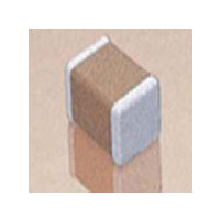
Manufacturer Part Number
08055E104MAT2A
Description
Capacitor, Ceramic; 0.1uF; Chip; Case 0805; +/-20%; 50WVDC; SMD; Z5U; 100000 Mohm; 0.05I
Manufacturer
AVX Corporation
Series
0805r
Specifications of 08055E104MAT2A
Tolerance (+ Or -)
20%
Voltage
50VDC
Temp Coeff (dielectric)
Z5U
Operating Temp Range
10C to 85C
Mounting Style
Surface Mount
Construction
SMT Chip
Case Style
Ceramic Chip
Failure Rate
Not Required
Wire Form
Not Required
Product Length (mm)
2.01mm
Product Depth (mm)
1.25mm
Product Height (mm)
1.3mm
Product Diameter (mm)
Not Requiredmm
Capacitance
.1uF
Package / Case
0805
Brand/series
AVX
Case Code
0805
Case Size
0805
Dielectric Strength
No breakdown or visual defects
Insulation Resistance
100000 Megohms
Length
0.079 in. ± 0.008 in.
Material, Element
Ceramic
Package Type
0805
Temperature, Operating, Maximum
125 °C
Temperature, Operating, Minimum
-55 °C
Termination
SMT
Tolerance
±20 %
Voltage, Rating
50 VDC
Width
0.049 in. ± 0.008 in.
Voltage Rating
50 Volts
Operating Temperature Range
+ 10 C to + 85 C
Temperature Coefficient / Code
Z5U
Product
General Type MLCCs
Dimensions
0.049 in W x 0.079 in L x 0.930 mm H
Termination Style
SMD/SMT
Lead Free Status / RoHS Status
Compliant


General Description
The
0.3 A/ns, and up to 10A/ns. At 0.3 A/ns, 100pH of parasitic
inductance can cause a voltage spike of 30mV. While this
does not sound very drastic, with the Vcc for microproces-
sors decreasing at the current rate, this can be a fairly large
percentage.
Another important, often overlooked, reason for knowing
the parasitic inductance is the calculation of the resonant
frequency. This can be important for high frequency, by-
pass capacitors, as the resonant point will give the most
signal attenuation. The resonant frequency is calculated
from the simple equation:
Insulation Resistance – Insulation Resistance is the resis-
tance measured across the terminals of a capacitor and
consists principally of the parallel resistance R
the equivalent circuit. As capacitance values and hence the
area of dielectric increases, the I.R. decreases and hence
the product (C x IR or RC) is often specified in ohm farads
or more commonly megohm-microfarads. Leakage current
40
dt
di
f
seen in current microprocessors can be as high as
res
=
2
1
LC
P
shown in
is determined by dividing the rated voltage by IR (Ohm’s
Law).
Dielectric Strength – Dielectric Strength is an expression
of the ability of a material to withstand an electrical stress.
Although dielectric strength is ordinarily expressed in volts, it
is actually dependent on the thickness of the dielectric and
thus is also more generically a function of volts/mil.
Dielectric Absorption – A capacitor does not discharge
instantaneously upon application of a short circuit, but
drains gradually after the capacitance proper has been dis-
charged. It is common practice to measure the dielectric
absorption by determining the “reappearing voltage” which
appears across a capacitor at some point in time after it has
been fully discharged under short circuit conditions.
Corona – Corona is the ionization of air or other vapors
which causes them to conduct current. It is especially
prevalent in high voltage units but can occur with low voltages
as well where high voltage gradients occur. The energy
discharged degrades the performance of the capacitor and
can in time cause catastrophic failures.
Related parts for 08055E104MAT2A
Image
Part Number
Description
Manufacturer
Datasheet
Request
R

Part Number:
Description:
Manufacturer:
AVX Corporation
Datasheet:
Part Number:
Description:
Manufacturer:
AVX Corporation
Datasheet:
Part Number:
Description:
Manufacturer:
AVX Corporation
Datasheet:
Part Number:
Description:
Manufacturer:
AVX Corporation
Datasheet:
Part Number:
Description:
Manufacturer:
AVX Corporation
Datasheet: