GRM21BR71H104KA01L Murata, GRM21BR71H104KA01L Datasheet - Page 210
GRM21BR71H104KA01L
Manufacturer Part Number
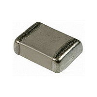
GRM21BR71H104KA01L
Description
CAPACITOR, 0805 100NF 50V CAPACITOR, 0805 100NF 50V
Manufacturer
Murata
Series
GRM21r
Specifications of GRM21BR71H104KA01L
Tolerance (+ Or -)
10%
Voltage
50VDC
Temp Coeff (dielectric)
X7R
Operating Temp Range
-55C to 125C
Mounting Style
Surface Mount
Construction
SMT Chip
Case Style
Ceramic Chip
Failure Rate
Not Required
Wire Form
Not Required
Product Length (mm)
2mm
Product Depth (mm)
1.25mm
Product Height (mm)
1.25mm
Product Diameter (mm)
Not Requiredmm
Capacitance
.1uF
Package / Case
0805
Voltage Rating, Dc
50V
Capacitor Dielectric Type
CERAMIC MULTI-LAYER
Tolerance,
10%
Tolerance, -
10%
Temp, Op. Max
125(DEGREE C)
Temp,
ROHS COMPLIANT
Lead Free Status / RoHS Status
Compliant
Available stocks
Company
Part Number
Manufacturer
Quantity
Price
Company:

Part Number:
GRM21BR71H104KA01L
Manufacturer:
MURATA
Quantity:
640 000
Company:
Part Number:
GRM21BR71H104KA01L
Manufacturer:
MURATA
Quantity:
400 000
Company:
Part Number:
GRM21BR71H104KA01L
Manufacturer:
MURATA
Quantity:
189 000
Part Number:
GRM21BR71H104KA01L 0805 X7R 104K 50V
Manufacturer:
MURATA/村田
Quantity:
20 000


!Note
• This PDF catalog is downloaded from the website of Murata Manufacturing co., ltd. Therefore, it’s specifications are subject to change or our products in it may be discontinued without advance notice. Please check with our
• This PDF catalog has only typical specifications because there is no space for detailed specifications. Therefore, please approve our product specifications or transact the approval sheet for product specifications before ordering.
sales representatives or product engineers before ordering.
!Note
3. Fail-safe
4. Test Condition for AC Withstanding Voltage
(1) Test Equipment
(2) Voltage Applied Method
FAILURE TO FOLLOW THE ABOVE CAUTIONS MAY
RESULT, WORST CASE, IN A SHORT CIRCUIT AND
CAUSE FUMING OR PARTIAL DISPERSION WHEN THE
PRODUCT IS USED.
Failure of a capacitor may result in a short circuit. Be sure
to provide an appropriate fail-safe function such as a fuse
on your product to help eliminate possible electric shock,
fire, or fumes.
Please consider using fuses on each AC line if the
capacitors are used between the AC input lines and earth
(line bypass capacitors), to prepare for the worst case,
such as a short circuit.
Tests for AC withstanding voltage should be made with
equipment capable of creating a wave similar to a
50/60 Hz sine wave.
If the distorted sine wave or overload exceeding the
specified voltage value is applied, a defect may be
caused.
The capacitor's leads or terminals should be firmly
connected to the output of the withstanding voltage test
equipment, and then the voltage should be raised from
near zero to the test voltage. If the test voltage is applied
directly to the capacitor without raising it from near zero,
it should be applied with the zero cross.* At the end of the
test time, the test voltage should be reduced to near zero,
and then the capacitor's leads or terminals should be
taken off the output of the withstanding voltage test
equipment. If the test voltage is applied directly to the
capacitor without raising it from near zero, surge voltage
may occur and cause a defect.
*ZERO CROSS is the point where voltage sine wave
- See the figure at right -
Continued from the preceding page.
passes 0V.
• Please read rating and !CAUTION (for storage, operating, rating, soldering, mounting and handling) in this catalog to prevent smoking and/or burning, etc.
• This catalog has only typical specifications because there is no space for detailed specifications. Therefore, please approve our product specifications or transact the approval sheet for product specifications before ordering.
AC IN
0V
Voltage sine wave
zero cross
FUSE
!Caution
209
C02E.pdf
10.12.20
Related parts for GRM21BR71H104KA01L
Image
Part Number
Description
Manufacturer
Datasheet
Request
R

Part Number:
Description:
Murata Microblower 20x20 DCDC Driver Board - Samples Only
Manufacturer:
Murata
Part Number:
Description:
357-036-542-201 CARDEDGE 36POS DL .156 BLK LOPRO
Manufacturer:
Murata
Datasheet:
Part Number:
Description:
Manufacturer:
Murata
Datasheet:
Part Number:
Description:
Manufacturer:
Murata
Datasheet:
Part Number:
Description:
Manufacturer:
Murata
Datasheet:
Part Number:
Description:
Manufacturer:
Murata
Datasheet:
Part Number:
Description:
Manufacturer:
Murata
Datasheet:
Part Number:
Description:
Manufacturer:
Murata
Datasheet:
Part Number:
Description:
Manufacturer:
Murata
Datasheet:
Part Number:
Description:
BLM21BD751SN1On-Board Type (DC) EMI Suppression Filters
Manufacturer:
Murata
Datasheet:
Part Number:
Description:
BLM15AG100SN1On-Board Type (DC) EMI Suppression Filters
Manufacturer:
Murata
Datasheet:
Part Number:
Description:
NFE31PT222Z1E9On-Board Type (DC) EMI Suppression Filters
Manufacturer:
Murata
Datasheet:
Part Number:
Description:
Chip Coil
Manufacturer:
Murata
Datasheet:
Part Number:
Description:
Chip Coil
Manufacturer:
Murata
Datasheet: