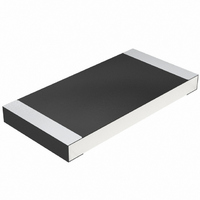
CRCW251251R0JNTG Vishay, CRCW251251R0JNTG Datasheet - Page 6

CRCW251251R0JNTG
Manufacturer Part Number
CRCW251251R0JNTG
Description
CRCW2512 200 51R 5% R67
Manufacturer
Vishay
Series
CRCWr
Type
Thick Filmr
Specifications of CRCW251251R0JNTG
Resistance (ohms)
51
Power (watts)
1W
Composition
Thick Film
Temperature Coefficient
±200ppm/°C
Tolerance
±5%
Size / Dimension
0.248" L x 0.124" W (6.30mm x 3.15mm)
Height
0.024" (0.60mm)
Lead Style
Surface Mount (SMD - SMT)
Package / Case
2512 (6432 Metric)
Resistance In Ohms
51.0
Case
2512 (6432 metric)
Power Rating(s)
1W
Resistance
51Ohm
Tolerance (+ Or -)
5%
Mounting Style
Surface Mount
Operating Temp Range
-55C to 155C
Case Style
Molded
Military Standard
Not Required
Failure Rate
Not Required
Product Length (mm)
6.3mm
Product Depth (mm)
3.15mm
Product Height (mm)
0.6mm
Power Rating
1 Watt
Termination Style
SMD/SMT
Voltage Rating
500 Volts
Operating Temperature Range
- 55 C to + 155 C
Dimensions
3.15 mm W x 6.3 mm L x 0.6 mm H
Product
Thick Film Resistors SMD
Lead Free Status / RoHS Status
Contains lead / RoHS non-compliant
Features
-
Lead Free Status / Rohs Status
No
Other names
CRCW2512 200 51R 5% R67
CRCW2512510JR67
CRCW2512510JR67
Document Number 20008
Revision 28-Apr-03
Pulse Rating P
1)
PERFORMANCE
TEST
Endurance Test at 70 C
IEC 60115-1 4.25.1; EIA-575
Endurance at UCT
IEC 60115-1 4.25.3
Overload Test
IEC 60115-1 4.13; EIA-575
Thermal Shock
IEC 60115-1 4.19; IEC 60068-2-14;
EIA-575
Damp Heat Steady State
IEC 60115-1 4.24; IEC 60068-2-3
Resistance to Soldering Heat
IEC 60115-1 4.18; IEC 600 68-2-20;
EIA-575
APPLICABLE SPECIFICATIONS
• CECC40000 / 40400 / 40401-004,-006,-007,-802
• EN140400 / IEC 60115 – 1
• EIA-575
Limits for change of resistance at test acc. to CECC
1000
0.01
100
10
0.1
1
10
-6
Secondary Conditions:
a) P P (peak pulse, single pulse
b)
c) Û see diagram (max pulse voltage)
u
< 70
10
-5
0
10
-4
10
For technical questions in Americas/Asia contact : ff2bresistors@vishay.com
-3
For technical questions in Europe contact : ff1aresistors@vishay.com
10
CONDITIONS OF TEST
1000 hours at 70 C 1.5 hours "ON" 0.5 hours "OFF"
1000 hours at 125 C without load
Short time overload, 2.5 x rated voltage or 2 x limiting element
voltage.
Rapid change between upper and lower category temperature
56 days at 40 C and 93% relative humidity
10 seconds at 260 C solder bath temperature
Thick Film, Rectangular, Chip Resistors
-2
Square Pulse in t
10
-1
1
1218
1206
2512
2010
0805
0603
0402
i
s
10
.
Pulse Rating P
Maximum Pulse Voltage
1400
1300
1200
1000
1100
0.10
0.01
100
900
800
700
600
500
400
200
300
100
10
1
0
10
10
1218
1206
0805
0603
0402
Secondary Conditions:
a) P P (permissible constant power
b)
c) Û see diagram (max pulse voltage)
-6
2010
1206/1218
-6
2512
0805
0603
0402
@ + 70 C)
u
< 70
10
10
-5
-5
P
70
10
10
-4
-4
10
10
-3
-3
0402
0603
Secondary Conditions:
a) P see diagrams (Pulse Rating)
b)
0.25
0.25
0.25
REQUIREMENTS IN %
1.0
1.0
1.0
10
10
u
< 70
-2
-2
0805
1206
1210
Square Pulse in t
Square Pulse in t
10
10
0.25
0.25
0.25
D...-CRCW
0.5
0.5
0.5
-1
-1
www.vishay.com
1218
2010
2512
1
1
1.0
1.0
0.5
0.5
1.0 <
0.5
Vishay
1)
i
i
0201
s
s
10
.
.
10
3.0
2.0
1.0
0.5
2.0
1.0
35


