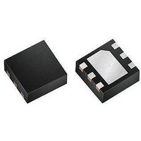
MAX9635ESA+T Maxim Integrated Products, MAX9635ESA+T Datasheet - Page 11

MAX9635ESA+T
Manufacturer Part Number
MAX9635ESA+T
Description
Optical Sensors - Board Mount Low-Power Ambient Li ght Sensor with ADC
Manufacturer
Maxim Integrated Products
Datasheet
1.MAX9635EDTT.pdf
(20 pages)
Specifications of MAX9635ESA+T
Supply Current
0.65 uA
Operating Supply Voltage
1.7 V to 3.6 V
Package / Case
uTDFN-6
Maximum Operating Temperature
+ 85 C
Minimum Operating Temperature
- 40 C
Lead Free Status / RoHS Status
Lead free / RoHS Compliant
The Lower Threshold register exponent with the four most significant bits of the mantissa sets the lower trip level for
interrupt functionality. This lower limit is relevant only if the INTE bit in the Interrupt Enable register is set. If the lux level
is below this light level for a time greater than that specified in the Threshold Timer register, the INTS bit in the Interrupt
Status register is set and the INT pin is pulled low.
Mantissa (LM[7:4]): Four most significant bits of mantissa lower threshold
Exponent (LE[3:0]): Exponent bits lower threshold
Lower lux threshold = 2
Exponent = 8xLE3 + 4xLE2 + 2xLE1 + LE0
Mantissa = 128xLM7 + 64xLM6 + 32xLM5 + 16xLM4
If the INTE bit = 1 and the ambient light level exceeds either threshold limit for a time longer than that specified by the
Threshold Timer register, then the INTS bit is set to 1 and the INT pin is pulled low.
The value in this register sets the time used to control this delay. A value of 0x00 in this register (with INTE bit = 1 in the
Interrupt Enable register) configures the IC to assert the interrupt pin as soon as the light level exceeds either threshold.
Time delay = (128xT7 + 64xT6 + 32xT5 + 16xT4 + 8xT3 + 4xT2 + 2xT1 + T0) x 100ms.
In auto mode configuration (default setting), CDR and
TIM bits are internally generated. The autoranging circuit
uses two different methods to change its sensitivity. For
light intensities greater than 700 lux, a current divider
reduces the photodiode’s current by a factor of 8. The
default, as in the previous example, is a division of 1:
current goes directly into the I to F converter. As light
intensity decreases, the autoranging circuit increases
the integration time from 100ms to 200ms to 400ms, or
to 800ms. The combination of the current divider and the
different integration times give the A/D a range 8 times
higher, as well as 8 times lower, than its nominal 16-bit
range. This gives a dynamic range of 22 bits or slightly
over 4,000,000 to 1.
In manual mode, the user has access to 4 bits (CDR and
TIM[2:0]) to override the autoranging circuitry. These
affect the integration time of the A/D and the current
division ratio. See the register description for manual
configuration mode (0x02, bit 6).
BIT 7
LE3
BIT 7
T7
Applications Information
BIT 6
LE2
(exponent)
Auto and Manual Modes
BIT 6
T6
BIT 5
LE1
x mantissa x 0.045
BIT 5
T5
Ambient Light Sensor with ADC
BIT 4
LE0
BIT 4
T4
BIT 3
Industry’s Lowest-Power
LM7
BIT 3
The IC has a user-friendly digital output format. It con-
sists of a 4-bit exponent followed by an 8-bit mantissa.
In its highest sensitivity mode, 1 count represents 0.045
lux. The mantissa has a maximum value of 255, and the
exponent has a maximum value of 14. This gives a maxi-
mum range: 255 x 2
maximum lux reading is 188,000 lux. Any reading greater
than that (i.e., exponent = 15) is considered to be an
overload. No conversion formulas are needed as in the
case of dual-diode ambient light sensors.
The IC’s output (registers 0x03 and 0x04) comprises a
12-bit result that represents the ambient light expressed
in units of lux.
Here is how lux is calculated:
Lux = (2
The exponent is a 4-bit number ranging from 0000 to
1110 (zero to 14).
The mantissa is an 8-bit number ranging from 0000 0000
to 1111 1111 (zero to 255).
T3
Lower Threshold High-Byte Register 0x06
BIT 2
(exponent)
LM6
BIT 2
T2
Threshold Timer Register 0x07
x mantissa) x 0.045
14
Data Format of Lux Reading
BIT 1
LM5
= 4,177,920. At 0.045 lux/LSB, the
BIT 1
T1
BIT 0
LM4
BIT 0
T0
REGISTER
REGISTER
ADDRESS
ADDRESS
0x06
0x07
11


