E3F2-D1C4-M 2M Omron, E3F2-D1C4-M 2M Datasheet - Page 18
E3F2-D1C4-M 2M
Manufacturer Part Number
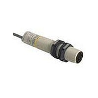
E3F2-D1C4-M 2M
Description
Photoelectric Sensors - Industrial NPN Diffuse 1M DC Pr ewrd NPB
Manufacturer
Omron
Datasheet
1.E3F2-D1C4-M_2M.pdf
(28 pages)
Specifications of E3F2-D1C4-M 2M
Proximity Sensor Type
Photoelectric
Output Type
NPN
Proximity Sensor Sensing Distance
100mm
Proximity Sensor Sensing Distance Range
50 to 300mm
Operating Temp Range
-25C to 55C
Operating Temperature Classification
Commercial
Operating Supply Voltage (min)
10V
Operating Supply Voltage (typ)
12/15/18/24V
Operating Supply Voltage (max)
30V
Lead Free Status / RoHS Status
Lead free / RoHS Compliant


NPN Output
18
E3F2-@C4-@
(except for
E3F2-10C4-@ and
E3F2-LS10C4-@)
E3F2-10C4-@
Photoelectric sensor
Model
–
ON when light is
incident.
(Light-ON)
ON when light is
interrupted. (Dark-
ON)
–
ON when light is
incident.
(Light-ON)
ON when light is
interrupted. (Dark-
ON)
transistor status
Output
E3F2
Test
input
Light
emission
Indicator
Incident
Interrupted
Incident
Interrupted
Incident
Interrupted
Incident
Interrupted
Output
indicator
(red)
Output
transistor
Load
(relay)
Output
indicator
(red)
Output
transistor
Load
(relay)
Output
indicator
(red)
Output
transistor
Load
(relay)
Output
indicator
(orange)
Output
transistor
Load
(relay)
Timing chart
Release
Release
Release
Release
Operate
Operate
Operate
Operate
OFF
OFF
OFF
OFF
OFF
OFF
OFF
OFF
OFF
OFF
OFF
ON
ON
ON
ON
ON
ON
ON
ON
ON
ON
ON
–
Connect the
pink (Pin ➁)
and brown (Pin
➀) cords or
open the pink
cord
(Pin ➁).
Connect the
pink (Pin ➁)
and blue
(Pin ➂) cords.
–
Connect the
pink (Pin ➁)
and brown (Pin
➀) cords or
open the pink
cord
(Pin ➁).
Connect the
pink (Pin ➁)
and blue
(Pin ➂) cords.
Connection
method
Through-beam emitter
Through-beam emitter
* Only on models
* Only on models
Output
indicator
Output
indicator
Light
indicator
Light
indicator
E3F2-R4C4-@ and
E3F2-D1C4-@
E3F2-R4C4-@ and
E3F2-D1C4-@
Orange
Orange
Red
Red
Red
Green
Green
Power
indicator
(red)
Stability
indicator*
Stability
indicator*
Connector Pin Arrangement
Connector Pin Arrangement
Connector Pin Arrangement
Connector Pin Arrangement
Connector Pin Arrangement
Main
circuit
Main
circuit
Main
circuit
Main
circuit
Main
circuit
Output circuit
2
2
2
2
2
Z
Z
1
1
3
3
Z
Z
1
3
1
3
D
D
1
D
D
3
: V
: V
: V
4
4
: V
4
4
4
Z
Z
Z
Z
= 36 V
= 36 V
= 36 V
= 36 V
4
4
1
3
2
1
3
2
1
4
3
2
1
4
3
2
Brown
Black
Blue
Pink
1
3
Brown
Black
Blue
Pink
Brown
Black
Blue
Pink
Brown
Black
Blue
Pink
Brown
Blue
Mode selection
Mode selection
Mode selection
Mode selection
100 mA
max.
100 mA
max.
100 mA
max.
100 mA
max.
10 to 30 VDC
10 to 30 VDC
10 to 30 VDC
10 to 30 VDC
10 to 30 VDC
Load
Load
Load
Load
0 V
0 V
0 V
0 V
0 V
Related parts for E3F2-D1C4-M 2M
Image
Part Number
Description
Manufacturer
Datasheet
Request
R

Part Number:
Description:
Photoelectric Sensors - Industrial NPN Diffuse 1M DC M1 2Conn NPB
Manufacturer:
Omron
Datasheet:

Part Number:
Description:
Photoelectric Sensors - Industrial NPN Diffuse 1M DC M1 2conn Plst
Manufacturer:
Omron
Datasheet:
Part Number:
Description:
Photoelectric Sensors - Industrial NPN Diffuse 1M DC Pr ewrd Plstc
Manufacturer:
Omron

Part Number:
Description:
G6S-2GLow Signal Relay
Manufacturer:
Omron Corporation
Datasheet:
Part Number:
Description:
Compact, Low-cost, SSR Switching 5 to 20 A
Manufacturer:
Omron Corporation
Datasheet:
Part Number:
Description:
Manufacturer:
Omron Corporation
Datasheet:
Part Number:
Description:
Manufacturer:
Omron Corporation
Datasheet:
Part Number:
Description:
Manufacturer:
Omron Corporation
Datasheet:
Part Number:
Description:
Manufacturer:
Omron Corporation
Datasheet:
Part Number:
Description:
Manufacturer:
Omron Corporation
Datasheet: