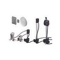
E39-S65A Omron, E39-S65A Datasheet - Page 5

E39-S65A
Manufacturer Part Number
E39-S65A
Description
Photoelectric Sensors - Industrial APERTURE 0.5 DI AMETER
Manufacturer
Omron
Specifications of E39-S65A
Lead Free Status / RoHS Status
Lead free / RoHS Compliant
E3Z-TA
Precautions
To ensure safe sensor operation, please follow these precautions.
I
Power Supply Voltage
Make sure that the power supply to the Sensor is within the rated
voltage range.
Load Short-Circuiting
Do not short-circuit the load, or the Sensor may be damaged.
Polarity
Correct polarity wiring is required to prevent damage to the sensor.
Connection without Load
Do not connect the power supply to the Sensor when no load
is connected, or the internal elements may explode or burn.
I
Do not use the Sensor in locations with explosive or flammable
gas.
I
Power Reset Time
When the E3Z-TA is turned ON, there is a 100 ms delay time
before operation. If the load and the Sensor are connected to
independent power supplies, be sure to turn ON the sensor before
turning ON the load.
I
M8 Metal Connector
• Turn OFF the power before disconnecting the sensor.
• Remove the connector cover before connecting or disconnecting
• Secure the connector cover by hand. Do not use pliers, or the
• The proper tightening torque range is between 0.3 and 0.4 N " m.
OMRON ELECTRONICS LLC
One East Commerce Drive
Schaumburg, IL 60173
1-800-55-OMRON
Cat. No. CEDSAX4
the metal connector.
connector may be damaged.
Wiring
Operating Environment
Settings
Connections
E3Z-TA
ALL DIMENSIONS SHOWN ARE IN MILLIMETERS.
To convert millimeters into inches, multiply by 0.03937. To convert grams into ounces, multiply by 0.03527.
11/01
(bracket sold separately)
OMRON ON-LINE
Global - http://www.omron.com
USA - http://www.omron.com/oei
Canada - http://www.omron.com/oci
Specifications subject to change without notice
Removal Method
• Press the upper portion of the Slit. (See area 1, shown below.)
• Then, disconnect the lower protruding portion of the Slit from the
I
• Hook the upper protruding portion of the Slit to the upper
• Then, press the lower protruding portion of the Slit onto
• Mounting views
Sensor and remove the Slit. (See area 2, shown below.)
indented mounting portion of the Sensor and adjust the
position of the Slit so that the Slit will be parallel to
the lens side of the Sensor. (See area 1, in the
illustration below.)
the indented mounting portion of the Sensor until the Slit
snaps in. (See area 2, shown below.)
Mounting and Adjusting Slits
Slit
Protruding
portion
Lower indented
mounting portion
Hook
Side view
Sensor
1
Upper indented
mounting portion
OMRON CANADA, INC.
885 Milner Avenue
Scarborough, Ontario M1B 5V8
416-286-6465
2
Front view
2
1
Printed in USA
E3Z-TA
5


