TFBS6711-TR3 Vishay, TFBS6711-TR3 Datasheet
TFBS6711-TR3
Specifications of TFBS6711-TR3


Related parts for TFBS6711-TR3


TFBS6711-TR3 Summary of contents
Page 1
... PARTS TABLE PART NUMBER TFBS6711-TR1 Oriented in carrier tape for side view surface mounting TFBS6711-TR3 Oriented in carrier tape for side view surface mounting TFBS6711-TT1 Oriented in carrier tape for top view surface mounting TFBS6711-TT3 Oriented in carrier tape for top view surface mounting ...
Page 2
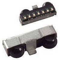
... Floating with a weak pull-up of 500 kΩ (typ.) in shutdown mode. The RXD output CC1 6 GND PINOUT TFBS6711 Weight PIN 1 19428 Fig Pinning www.vishay.com For technical questions within your region, please contact one of the following: 2 irdasupportAM@vishay.com, irdasupportAP@vishay.com, Low Profile Fast Infrared Transceiver (FIR, 4 Mbit/s) ® ...
Page 3
... CC1 CC2 pin amb T stg I (DC) IRED < (RP) on IRED I IREDA > allowed V CC1 IN th individual directive within the meaning of article 16(1) TFBS6711 Vishay Semiconductors MIN. TYP. MAX 0.5 6 500 125 - 260 125 600 - 0.5 6.5 - 0.5 5.5 CLASSIFICATION Class 1 Exempt th April 2006 Exempt www ...
Page 4
... TFBS6711 Vishay Semiconductors ELECTRICAL CHARACTERISTICS PARAMETERS TRANSCEIVER Supply voltage Dynamic supply current °C, not ambient light Shutdown supply current sensitive, detector is disabled in Shutdown supply current °C, not ambient light Operating temperature range Output voltage low Output voltage high Internal RXD pull-up ...
Page 5
... IRED = 3.6 V, α = 0°, 15° V CC1 TXD = low high t ropt t Input pulse width 217 ns, t 1.152 Mbit Input pulse width t < 80 µs t Input pulse width t ≥ 80 µs t TFBS6711 Vishay Semiconductors MIN. TYP. MAX. 225 275 350 500 t 100 L I 330 440 ...
Page 6
... Vishay Sales, Marketing or Application. MODE SWITCHING The TFBS6711 is in the SIR mode after power default mode, therefore the FIR data transfer rate has to be set by a programming sequence using the TXD and SD inputs as described below. The low frequency mode covers speeds up to 115 ...
Page 7
... Time (s) Fig Recommended Solder Profile for Sn/Pb Soldering Lead (Pb)-free, Recommended Solder Profile The TFBS6711 is a lead (Pb)-free transceiver and qualified for lead (Pb)-free processing. For lead (Pb)-free solder paste like Sn Ag Cu, there are two standard reflow (3.0-4.0) (0 ...
Page 8
... TFBS6711 Vishay Semiconductors TFBS6711 PACKAGE DIMENSIONS in millimeters 19612 Fig Package Drawing, Tolerances: Height + 0.1, - 0.2 mm, otherwise ± 0 not indicated Recommended Footprint Side View Application 5 x 0.95 = 4.75 0. Emitter Detector 19728 Design Rules for Optical Windows For optical windows see the application note on the web. ...
Page 9
... Document Number: 84676 For technical questions within your region, please contact one of the following: irdasupportAM@vishay.com, irdasupportAP@vishay.com, Rev. 1.7, 17-Sep-09 ® for IrDA Applications N W MIN. 1 (mm) (mm) 50 16.4 TFBS6711 Vishay Semiconductors W MAX. W MIN (mm) (mm) 22.4 15.9 www.vishay.com irdasupportEU@vishay.com MAX. 3 (mm) 19 ...
Page 10
... TFBS6711 Vishay Semiconductors TAPE DIMENSIONS in millimeters 19613 Fig Tape Drawing, TFBS6711 for Side View Mounting, Tolerance ± 0.1 mm www.vishay.com For technical questions within your region, please contact one of the following: 10 irdasupportAM@vishay.com, irdasupportAP@vishay.com, Low Profile Fast Infrared Transceiver (FIR, 4 Mbit/s) ® for IrDA ...
Page 11
... Low Profile Fast Infrared Transceiver (FIR, 4 Mbit/s) TAPE DIMENSIONS in millimeters 20416 Fig Tape Drawing, TFBS6711 for Top View Mounting, Tolerance ± 0.1 mm Document Number: 84676 For technical questions within your region, please contact one of the following: irdasupportAM@vishay.com, irdasupportAP@vishay.com, Rev. 1.7, 17-Sep-09 ® ...
Page 12
... Vishay product could result in personal injury or death. Customers using or selling Vishay products not expressly indicated for use in such applications their own risk and agree to fully indemnify and hold Vishay and its distributors harmless from and against any and all claims, liabilities, expenses and damages arising or resulting in connection with such use or sale, including attorneys fees, even if such claim alleges that Vishay or its distributor was negligent regarding the design or manufacture of the part ...