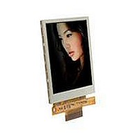
SDT032TFT Displaytech, SDT032TFT Datasheet - Page 7

SDT032TFT
Manufacturer Part Number
SDT032TFT
Description
TFT Displays & Accessories 3.2in TFT
Manufacturer
Displaytech
Datasheet
1.SDT032TFT-TS.pdf
(11 pages)
Specifications of SDT032TFT
Attached Touch Screen
No
Diagonal
3.2 in
Interface
Parallel
Interface Type
Parallel
Maximum Operating Temperature
+ 70 C
Minimum Operating Temperature
- 20 C
Operating Current
16.74 mA
Operating Temperature Range
- 20 C to + 70 C
Product
Displays
Supply Voltage
2.7 V to 2.9 V
Viewing Area (w X H)
50.6 mm x 66.8 mm
Pixel Density
240 x 320
Backlighting
White
Lead Free Status / RoHS Status
Lead free / RoHS Compliant
Available stocks
Company
Part Number
Manufacturer
Quantity
Price
Company:
Part Number:
SDT032TFT
Manufacturer:
Displaytech
Quantity:
135
4. Interface Description
Touch Screen FPC (only for DT032TFT-TS)
Displaytech Ltd
Pin no
15~32
41~45
Pin no
10
11
12
13
14
33
34
35
36
37
38
39
40
1
2
3
4
5
6
7
8
9
1
2
DB17~DB0
DOTCLK
VSYNC
HSYNC
Symbol
RESET
LEDA
LEDK
SHUT
GND
VDD
GND
DEN
SDO
SCK
PS2
PS1
PS0
PS3
WR
SDI
RD
DC
NC
CS
Symbol
X+
Y+
Level
2.8V
H/L
H/L
H/L
H/L
H/L
H/L
H/L
H/L
H/L
H/L
0V
0V
---
---
---
---
---
---
---
---
---
---
-
LCD MODULE DT032TFT / DT032TFT-TS Version: 3.0
LED Backlight Anode
LED Backlight Cathode
Ground
Power supply
When using the RGB interface, it is a input pin put the driver into sleep mode. A
sharp falling edge must be provided to such pin when IC power on.
Connect to VDDIO for sleep mode
Connect to VSS for normal operating mode
This pin has no effect in system interface and should be connected to VDDIO / VSS
Reset signal pin
Frame synchronization signal.
- Fixed to VDDIO or VSS if not used
Line synchronization signal.
- Fixed to VDDIO or VSS if not used
Dot-clock signal and oscillator source. A non-stop external clock must be provided
to that pin even at front or black porch non-display period.
Display enable pin from controller. Data will be treated as dummy regardless the
DEN status during front/back porch setting at registers R16 and R17.
Data bus
68 system: Enable (E)
80 system: Read signal (/RD)
Serial: Not used
68 system: Read when high, Write when low (/WR)
80 system: Write signal (WR)
Serial: Not used
Register select signal
Data output pin in serial mode.
- Leave it OPEN when not used
Data input pin in serial mode.
Leave it OPEN when not used
Clock pin of serial interface.
- Leave it OPEN when not used
Chip select signal
Ground
No connection
PS3
1
1
1
1
1
1
0
0
0
0
0
0
0
Pin no
3
4
PS2
1
1
0
0
0
0
1
1
1
1
0
0
0
PS1
1
1
1
1
0
0
1
1
0
0
1
1
0
Symbol
PS0
1
0
1
0
1
0
1
0
1
0
1
0
1
X-
Y-
Description
3 wire SPI
4 wire SPI
6800 parallel, 16 bit
6800 parallel, 8 bit
8080 parallel, 16 bit
8080 parallel, 8 bit
6800 parallel, 18 bit
6800 parallel, 9 bit
8080 parallel, 18 bit
8080 parallel, 9 bit
Reserved
16 bit RGB + 4 wire SPI
18 bit RGB + 4 wire SPI
Interface Mode
P7 of 11


