NHD-4.3-480272YF-ATXI#-1 Newhaven Display, NHD-4.3-480272YF-ATXI#-1 Datasheet
NHD-4.3-480272YF-ATXI#-1
Specifications of NHD-4.3-480272YF-ATXI#-1


Related parts for NHD-4.3-480272YF-ATXI#-1


NHD-4.3-480272YF-ATXI#-1 Summary of contents
Page 1
... User’s Guide NHD-4.3-480272YF-ATXI#-1 LCM (Liquid Crystal Display Module) For product support, contact Newhaven Display Newhaven Display International 2511 Technology Drive, #101 Elgin, Illinois 60123 Tel: (847) 844-8795 Fax: (847) 844-8796 NHD-4.3-480272YF-ATXI#-1 December 18, 2008 ...
Page 2
Date Rev. No. May.16.2006 000 May.25.2006 001 June.11.2006 002 Aug.08.2008 003 Revision History Page Rev.000 was first issues. 16 Back-Light was inserted. 4 Inversion mode was corrected. 8 Viewing angle were corrected. Changed pinout to include backlight and touchpanel. Summary ...
Page 3
Contents General Description 1. Absolute Maximum Ratings 1.1 Absolute Ratings Of Environment 1.2 Electrical Absolute Ratings 2. Optical Characteristics 3. Electrical Characteristics 3.1 TFT-LCD Module 3.2 Back-light Unit . Block Diagram 4. 4.1 TFT-LCD Module(Interface System Structure) with Back Light ...
Page 4
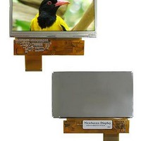
... General Description * Description NHD-4.3-480272YF-ATXI#- transmissive type color TFT (Thin Film Transistor) liquid crystal display (LCD) that uses amorphous silicon TFT as a switching devices. This model is composed of a TFT-LCD module, a driver circuit and a back-light unit. The resolution of a 4.3" contains 480x272(RGB) dots and can display up to 16.7M colors ...
Page 5
General information Items Display area 95.04(H) x 53.856(V) (4.3" diagonal) Driver element Display colors Number of dots Pixel arrangement Pixel pitch Display mode Viewing direction * Mechanical information Item Horizontal(H) Module Vertical(V) size Depth(D) Weight Note (1) Not include ...
Page 6
Absolute Maximum Ratings 1.1 Absolute Ratings Of Environment ITEM Storage Temperature Operating Temperature Note(1) 90%RH maximum humidity, 60℃ maximum wet-bulb temperature (2) When operated at a temperature lower than 0℃, the LCD worked slowly and the screen appeared low-contrast ...
Page 7
Electrical Absolute Ratings (1) TFT-LCD Module Item Input voltage (2) Back-Light Unit Item Current Note (1) Permanent damage to the device may occur if maximum values are exceeded or reverse voltage is loaded. Functional operation should be restricted to ...
Page 8
Optical Characteristics The following items are measured under stable conditions. The optical characteristics should be measured in a dark room or equivalent state with the methods shown in Note (1). Measuring equipment: LCD-5000, BM-5A, BM-7, PR-650, EZ-Contrast Item Symbol ...
Page 9
Note (1) Test Equipment Setup After stabilizing and leaving the panel alone at a given temperature for 30 min , the measurement should be executed. and dark room. 30 min after lighting the back-light. This should be measured in the ...
Page 10
Note (2) Definition of Contrast Ratio (C/R) : Ratio of gray max (Gmax) & gray min (Gmin) at the center point G max = CR G min Note (3) Definition of Luminance of White : Luminance of white at the ...
Page 11
Note (6) Definition of Viewing Angle : Viewing angle range (CR ≥ θ = o’clock direction φ Normal Line φ θ ...
Page 12
Electrical Characteristics 3.1 TFT-LCD Module ITEM Logic supply voltage Vsync Frequency Hsync Frequency Main Frequency White Power Dissipation Black Note (1). f =60Hz, f =9.2MHZ, VDD=3.3V V DCLK Note (2). Power Dissipation check patter a) White Pattern Symbol Min. ...
Page 13
Back-Light unit The back-light system is an edge-lighting type with seven white LED(Light Emitting Diode) s. Item Symbol LEDs Current Power Consumption P Note (1) Seven LEDs serial type. (2) Where mA Min. Typ. ...
Page 14
Block Diagram 4.1 TFT-LCD Module (Interface System Structure) with Back Light Unit 4.2 Back-light Unit VLED-ANODE VLED-CATHODE ...
Page 15
INTERFACE PIN CONNECTIONS PIN SYMBOL 1 LED- Cathode of LED backlight 2 LED+ Anode of LED backlight 3 GND Ground for the logic and analog circuit 4 VCC A power supply for the internal logic circuit and for the ...
Page 16
Input Signal,Basic Display Colors and Gray Scale of Each Colors COLOR DISPLAY RED BLACK 0 ...
Page 17
PIXEL FORMAT ...
Page 18
INTERFACE TIMING 6-1. Vertical timing Signal Symbol fFRM Frame Frequency VSYNC(Frame) Period VCYC VSYNC Low width Vertical Display Period Vertical Back porch Vertical Front porch 6-2. Horizontal timing Signal Symbol HCYC HSYNC(1H) Period HSYNC Low width Horizontal Display Period ...
Page 19
...
Page 20
AC characteristics Parameter VSYNC,HSYNC setup time ENABLE (DE) setup time ENABLE (DE) hold time DOTCLK "Low" level pulse width DOTCLK "High" level pulse width DOTCLK cycle time Data setup time Data hold time DOTCLK,VSYNC,HSYNC clock rise/fall time ※ Operating ...
Page 21
...
Page 22
PON timing characteristics. Item Symbol PON setup t PONSV (SYNC mode) ※ Operating at VDD=2.25~2. -40 ℃ ~+85 ℃ Min. Typ Max. unit - DOTCLK ...
Page 23
Power On/Off Sequenc prevent a latch- operation of the LCD module, the power on/off sequence should be as the diagram below. Power Supply VDD Interface Signal Display On/Off Signal Power Supply for LED unit ...
Page 24
...
Page 25
Packing Note (1) Total : Case: Approx. : TBD Kg Box: Approx. : TBD Kg (2) Size : Case: 490(W) x 342(D) x 58(H) Box: 505(W) x 355(D) x 312(H) (3) Place the panels in the ...
Page 26
Others ...
Page 27
General Precautions 11.1 Handling (a) When the module is assembled, it should be attached to the system firmly. Be careful not to twist and bend the module. (b) Refrain from strong mechanical shock and / or any force to ...