LCD2041 Matrix Orbital, LCD2041 Datasheet - Page 10
LCD2041
Manufacturer Part Number
LCD2041
Description
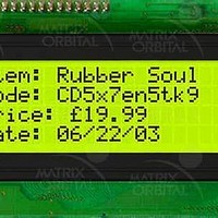
LCD Character Display Modules Yel/Grn Background Black Text
Manufacturer
Matrix Orbital
Datasheet
1.LCD2041.pdf
(30 pages)
Specifications of LCD2041
Character Count X Line
20 x 4
Module Size (w X H X T)
98 mm x 60 mm x 27.5 mm
Features
I2C LCD with software controlled contrast
Voltage Rating
4.75 VDC to 5.25 VDC
Operating Temperature Range
- 20 C to + 70 C
Backlight Type
LED Yellow-Green
Interface
I2C


The RS-232 connector on the PC cable is wired so that a standard “straight through” 9 pin D-sub cable may
be used to connect the module to a standard serial port such as COM ports on PCs. Note that this device
complies with the EIA232 standard in that it uses signal levels from ± 3V to ± 12V. It will not operate
correctly at TTL (0 to +5V) levels.
2.2.2 Applying Power via the RS-232 Connector
The power connector on the PC cable is wired as shown in Figure 2-7. Power may be provided to the
module by pin 9 of the DB9 connector instead of through the 4-pin SIP. If power is to be applied using the
DB9, it must be a regulated 5Vdc supply. Note: This applies to wide voltage units (V and VPT
extensions) as well as to standard 5 volt units.
To use pin 9 as the power source, the user must solder the 5 volt jumper pad beside the DB9 connector. If
you have any further questions or concerns don’t hesitate to contact Matrix Orbital at support@matrix-
orbital.com.
Warning: Use this method of power up at your own risk. Application of a voltage to pin 9 greater
than 5.5 volts will cause immediate destruction of unit and void the warranty.
2.2.3 Configuring RS-232 and I
RS-232 baud rate and I
LCD2041 rev 2
Pin Number
2
C address are configured by means of jumpers (see ).
2
3
5
Data from LCD
Data to LCD
Direction
Figure 2-8 RS-232 jumpers
2
C
-
10
Data out (LCD)
Data in (LCD)
Description
Ground
LCD Host
gnd
Rx
Tx
gnd
Rx
Tx
Related parts for LCD2041
Image
Part Number
Description
Manufacturer
Datasheet
Request
R

Part Number:
Description:
DISPLAY
Manufacturer:
Matrix Orbital
Datasheet:

Part Number:
Description:
LCD ACCY VFD FILTER 20X2 BLUE
Manufacturer:
Matrix Orbital
Datasheet:
Part Number:
Description:
LCD ACCY VFD FILTER 20X2 RED
Manufacturer:
Matrix Orbital
Datasheet:
Part Number:
Description:
LCD ACCY VFD FILTER 20X2 GREEN
Manufacturer:
Matrix Orbital
Datasheet:
Part Number:
Description:
LCD ACCY VFD FILTER 20X4 BLUE
Manufacturer:
Matrix Orbital
Datasheet:
Part Number:
Description:
LCD ACCY VFD FILTER 20X4 RED
Manufacturer:
Matrix Orbital
Datasheet:
Part Number:
Description:
LCD ACCY VFD FILTER 20X4 GREEN
Manufacturer:
Matrix Orbital
Datasheet:

Part Number:
Description:
DISPLAY
Manufacturer:
Matrix Orbital
Datasheet:

Part Number:
Description:
DISPLAY
Manufacturer:
Matrix Orbital
Datasheet:


Part Number:
Description:
VFD DISPLAY 16X2 SER/I2C
Manufacturer:
Matrix Orbital
Datasheet:

Part Number:
Description:
VFD ALPHA/NUM DISPL 20X2 SER/I2C
Manufacturer:
Matrix Orbital
Datasheet:

Part Number:
Description:
VFD ALPHA/NUM DISPL 16X2 SER/I2C
Manufacturer:
Matrix Orbital
Datasheet:
Part Number:
Description:
VFD ALPHA/NUM DISPL 20X2 SER/I2C
Manufacturer:
Matrix Orbital
Datasheet: