NMTG-S12864EFYHSGY-10B Microtips Technology, NMTG-S12864EFYHSGY-10B Datasheet - Page 9
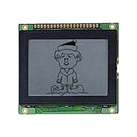
NMTG-S12864EFYHSGY-10B
Manufacturer Part Number
NMTG-S12864EFYHSGY-10B
Description
LCD Graphic Display Modules & Accessories Yellow Transflective Yl/Gn LED Backlight
Manufacturer
Microtips Technology
Datasheet
1.NMTG-S12864EFYHSGY-10B.pdf
(20 pages)
Specifications of NMTG-S12864EFYHSGY-10B
Pixel Density
128 x 64
Fluid Type
STN
Module Size (w X H X T)
78 mm x 70 mm x 12.4 mm
Viewing Area (w X H)
62 mm x 44 mm
Backlighting
LED
Background Color
Yellow, Green
Operating Temperature Range
- 20 C to + 70 C
Attached Touch Screen
No
Product
Graphic LCD Module
Style
LCD Graphic Display
Display Mode
Transflective
Lead Free Status / RoHS Status
Lead free / RoHS Compliant


3. Optical Specifications
Messrs.
Product Specification
3.1 LCD Driving Voltage Recommended
3.2 Optical Characteristics
LCD Driving Voltage Note 1
Contrast Ratio Note 1
Viewing Angle
(Shown in 3.3)
Response
Time
Note 1:
Note 1:
Note 2:
Note 3:
Note 4:
Parameter
Parameter
The time that the luminance level reaches 90% of the saturation level from 0% when ON signal is
applied.
The time that the luminance level reaches 10% of the saturation level from 100% when OFF
signal is applied.
Voltage (Applied actual waveform to LCD Module) for the best contrast. The range of minimum
and maximum shows tolerance of the operating voltage. The specified contrast ratio and
response time are not guaranteed over the entire range.
CR = L
L
Definition of Driving Voltage V
applied to the LCD Panel at /A Duty - 1/B Bias (A: Duty Number, B: Bias Number). Driving
voltage V
Vth1:
Vth2:
Contrast ratio is defined as follows.
ON
Rise Note 2
Decay Note 3
: Luminance of the ON segments, L
OFF
D
/ L
is defined s follows: V
The voltage VO-P that should provide 50% of the saturation level in the luminance at
the segment which the ON signal is applied to.
The voltage VO-P that should provide 50% of the saturation level in the luminance at
the segment which the OFF signal is applied to.
ON
Model: NMTG-S12864EFYHSGY-10B
Symbol
Symbol
V
Front
Right
Back
DD
Left
T
T
C
Vo -p
OFF
ON
-V
Selected state
1 / (f
(ON SIGNAL)
O
F
D
. Assuming that the typical driving waveforms shown below are
x A)
D
= (Vth1+Vth2) / 2
Ta=25 °C, 1/64 Duty, 1/9 Bias, V
θ = 0°, φ = 0°
OFF
θ
θ
Ta = -20 °C
Conditions
Ta = 25 °C
Ta = 70 °C
Conditions
θ
θ
L
F
B
R,
, φ = 180°
, φ = 270°
: Luminance of the OFF segments
, φ = 90°
, φ = 0°
--
--
Unselected state
(OFF SIGNAL)
1 / f
F
Min.
9.90
9.40
8.70
Min.
--
--
--
--
--
--
--
Rev. No.
(B-2) x Vo-p / B
A
DD
= 5V (Note 4), θ = 0°, φ =270°
10.2
9.70
9.00
Typ.
Typ.
250
300
9.3
40
30
35
50
Issued Date.
Jun. 20, 08
Max.
Max.
10.5
10.0
750
900
9.30
--
--
--
--
--
Units
msec
msec
Units
deg.
deg.
deg.
deg.
V
V
V
--
9 / 20
Page.
Related parts for NMTG-S12864EFYHSGY-10B
Image
Part Number
Description
Manufacturer
Datasheet
Request
R

Part Number:
Description:
TFT Displays & Accessories 7.0 TFT WVGA Tch Screen 180 Nits
Manufacturer:
Microtips Technology
Datasheet:

Part Number:
Description:
LCD Character Display Modules 20x2 VLCD Character White LED Backlight
Manufacturer:
Microtips Technology
Datasheet:

Part Number:
Description:
LCD Character Display Modules 20x2 VLCD Character Green LED Backlight
Manufacturer:
Microtips Technology
Datasheet:

Part Number:
Description:
LCD Character Display Modules 20x2 VLCD Character Red LED Backlight
Manufacturer:
Microtips Technology
Datasheet:

Part Number:
Description:
LCD Character Display Modules Gray Transflective White LED Backlight
Manufacturer:
Microtips Technology
Datasheet:

Part Number:
Description:
LCD Character Display Modules Gray Reflective
Manufacturer:
Microtips Technology

Part Number:
Description:
LCD Character Display Modules Yl/Grn Transflective Yl/Grn LED Backlight
Manufacturer:
Microtips Technology
Datasheet:
Part Number:
Description:
LCD Character Display Modules Yl/Grn Reflective
Manufacturer:
Microtips Technology
Part Number:
Description:
LCD Character Display Modules Gray Transflective Yl/Grn LED Backlight
Manufacturer:
Microtips Technology

Part Number:
Description:
LCD Character Display Modules Gray Reflective
Manufacturer:
Microtips Technology
Datasheet:
Part Number:
Description:
TFT Displays & Accessories 7.0 TFT WVGA Tch Screen 180 Nits
Manufacturer:
Microtips Technology
Datasheet:

Part Number:
Description:
TFT Displays & Accessories 5.7 TFT VGA WHITE LED 350 Nits
Manufacturer:
Microtips Technology
Datasheet:

Part Number:
Description:
TFT Displays & Accessories 3.5 TFT W/ Touch screen
Manufacturer:
Microtips Technology
Datasheet:
Part Number:
Description:
TFT Displays & Accessories 320 x 240 TFT 3.5 diag
Manufacturer:
Microtips Technology
Datasheet:

Part Number:
Description:
TFT Displays & Accessories 2.4 TFT ILI9325 TFT driver
Manufacturer:
Microtips Technology
Datasheet: