51CAD-E24-A20L Bourns Inc., 51CAD-E24-A20L Datasheet - Page 2
51CAD-E24-A20L
Manufacturer Part Number
51CAD-E24-A20L
Description
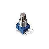
PANEL CONTROL - 1/2" (12.5MM) SQ 1-TURN
Manufacturer
Bourns Inc.
Series
51r
Type
Potentiometerr
Datasheet
1.51CAD-E24-A15L.pdf
(3 pages)
Specifications of 51CAD-E24-A20L
Resistance (ohms)
100K
Power (watts)
1W
Tolerance
±10%
Temperature Coefficient
±150ppm/°C
Number Of Turns
Single
Rotation
290°
Adjustment Type
Side Adjustment
Resistive Material
Cermet
Termination Style
Through Hole
Actuator Length
19.05mm
Actuator Type
Slotted Shaft
Actuator Diameter
3.18mm
Package / Case
Square - 0.492" L x 0.350" W x 0.521" H (12.50mm x 8.89mm x 13.23mm)
Resistance
100 KOhms
Power Rating
1 Watt
Taper
Linear
Element Type
Cermet
Shaft Type
Slotted
Shaft Length
3/4 in
Shaft Diameter
1/8 in
Operating Temperature Range
+ 1 C to + 125 C
Dimensions
12.5 mm W x 9.53 mm L x 13.25 mm H
Product
Potentiometers
Voltage Rating
500 Volts
Mounting Type
Panel
Power, Rating
1 W
Lead Free Status / RoHS Status
Lead free / RoHS Compliant
Lead Free Status / RoHS Status
Lead free / RoHS Compliant
Available stocks
Company
Part Number
Manufacturer
Quantity
Price
Company:

Part Number:
51CAD-E24-A20L
Manufacturer:
BOURNS
Quantity:
1 000


(.036 ± .002)
0.91 ± .051
PACKAGE DIMENSIONS
PACKAGE DIMENSIONS PCB MOUNTING BRACKET
ANTI-ROTATION LUG
(Style "A", 90 CW Shown)
(.250 ± .010)
Product Dimensions
6.35 ± .25
(.300 ± .012)
51/53 - Sealed 1/2 ” (12.5 mm) Square Control
7.62 ± 0.30
(SINGLE, DUAL AND TRIPLE MODULE SHOWN)
AVAILABLE IN 1 THROUGH 6 MODULE VERSIONS.
AVAILABLE IN 1 THROUGH 6 MODULE VERSIONS.
DIMENSIONS:
(.950 ± .021)
(.950 ± .013)
24.15 ± 0.33
24.13 ± 0.33
(.650 ± .010)
16.51 ± 0.25
(.0118)
(.300 ± .012)
0.30
7.62 ± 0.30
(.031 ± .012)
0.80 ± 0.30
(INCHES)
(.300 ± .012)
7.62 ± 0.30
(.300 ± .012)
7.62 ± 0.30
MM
(.350 ± .007)
8.89 ± 0.18
(.200 ± .012)
5.08 ± 0.30
(.052 ± .010)
1.32 ± 0.25
"L"
"L"
(.200 ± .012)
5.08 ± 0.30
( .025)
( .025)
.64
.64
(.060)
(.016)
1.52
0.41
(.224)
5.70
2 X
( .016 ± .002)
3 X
(.432)
.41 ± .05
11.00
(.432)
11.00
2 X
(.026 ± .002)
(.029)
0.74
(.029)
.66 ± .05
0.74
(.200)
(.100)
DIA.
5.08
2.54
SHAFT FLAT
ORIENTATION
DIA.
( .100)
2.54
MODEL 51
TERMINAL SPACING
(.492)
(.492)
12.5
12.5
132 ° ± 5 ° CCW END
(.100)
2.54
(.100)
2.54
(.200)
5.08
(.246)
(.260 ± .015)
(.260 ± .015)
(.246)
6.25
6.60 ±0.38
6.60 ±0.38
6.25
(.275)
(.275)
7.00
7.00
Customers should verify actual device performance in their specifi c applications.
SUGGESTED PANEL LAYOUTS
The Model 50 can be used with either
of the two panel layouts shown below.
(DOUBLE MODULE FRONT AND REAR BRACKET SHOWN)
(.094)
(.100)
2.40
(.036)
TYP.
2.54
0.90
CCW
BUSHING DIAMETER
FOR TOLERANCES SHOWN: .XX = ±
SOLDER LUG TERMINALS
ELECTRICAL SCHEMATIC
(.050)
4 PLCS.
1.27
DIA.
1
( .031)
(.250)
0.80
6.35
(.244)
6.20
3
(.087)
2.20
Specifi cations are subject to change without notice.
SHAFT DIMENSIONS ±
MODEL 53
(.300)
2
6 PLCS.
(.040)
7.62
1.02
DIA.
1
2 X
(.185)
2
4.70
BUSHING DIAMETER
(.071)
1.80
.XXX = ±
( .031)
0.80
(.250)
(.010)
(.005)
(1/32)
6.35
.25
.13
.80
(.109)
2.77
3
(.197 ± .002)
5.0 ± 0.51
(.200)
(.052)
CW
5.08
1.32
FMS
C L OF POT
Related parts for 51CAD-E24-A20L
Image
Part Number
Description
Manufacturer
Datasheet
Request
R

Part Number:
Description:
POT 10K OHM CERMET 1W
Manufacturer:
Bourns Inc.
Datasheet:
Part Number:
Description:
POT 10K OHM CERMET 1W
Manufacturer:
Bourns Inc.
Datasheet:
Part Number:
Description:
POT 10K OHM COND PLAST 1/2W
Manufacturer:
Bourns Inc.
Datasheet:
Part Number:
Description:
POTENTIOMETER, ROTARY, 12.5MM
Manufacturer:
Bourns Inc.
Datasheet:

Part Number:
Description:
PANEL CONTROL - 1/2" (12.5MM) SQ 1-TURN
Manufacturer:
Bourns Inc.
Datasheet:
Part Number:
Description:
PANEL CONTROL - 1/2" (12.5MM) SQ 1-TURN
Manufacturer:
Bourns Inc.
Datasheet:
Part Number:
Description:
PANEL CONTROL - 1/2" (12.5MM) SQ 1-TURN
Manufacturer:
Bourns Inc.
Datasheet:

Part Number:
Description:
PANEL CONTROL - 1/2" (12.5MM) SQ 1-TURN
Manufacturer:
Bourns Inc.
Datasheet:

Part Number:
Description:
Manufacturer:
Bourns Inc.
Datasheet:
Part Number:
Description:
Panel Mount Potentiometers 1/2 100K 20% Square Sealed
Manufacturer:
Bourns Inc.
Datasheet:

Part Number:
Description:
Manufacturer:
Bourns, Inc.
Datasheet:
Part Number:
Description:
11mm Potentiometer
Manufacturer:
Bourns, Inc.
Datasheet: