01M1002SFC3 Vishay, 01M1002SFC3 Datasheet

1M1002-C3 E06 E3

01M1002SFC3

Manufacturer Part Number
01M1002SFC3
Description
1M1002-C3 E06 E3
Manufacturer
Vishay
Type
NTCr
Datasheet

Specifications of 01M1002SFC3

Mounting Style
Through Hole
Pin Count
2
Screening Level
Commercial
Resistance @ 25c
10kohm
Operating Temperature Min Deg. C
0C
Operating Temperature Max Deg. C
70C
Product Length (mm)
Not Requiredmm
Product Depth (mm)
Not Requiredmm
Peak Reflow Compatible (260 C)
Yes
Rohs Compliant
Yes
Lead Free Status / RoHS Status
Lead free / RoHS Compliant
M, C, T
Vishay Dale
DESCRIPTION
Models M, C, and T are conformally coated, leaded thermistors for standard PC board mounting or assembly in probes.
The coating is baked-on phenolic for durability and long-term stability. Models M and C have tinned solid copper leads.
Model T has solid nickel wires with Teflon
DIMENSIONS in inches (millimeters)
www.vishay.com
104
BODY DIA.
Global Part Numbering: 01C2001SPC3 for CURVE TRACKING THERMISTORS
CURVE
PRODUCT TYPE
GLOBAL PART NUMBER INFORMATION
Global Part Numbering: 01C2001FP for POINT MATCHED THERMISTORS
MAX.
01
02
04
08
09
17
CURVE
01
02
03
04
07
08
09
12
13
14
17
GLOBAL MODEL
0
M
C
T
0
NTC Thermistors, Radial Leaded and Coated
GLOBAL MODEL
1
1
TINNED COPPER WIRE
M
C
C
Type M
T
RESISTANCE VALUE
Type C
Type T
C
CLEAN LEAD LENGTH
1.5 (36.1) MIN.
2001 = 2K
2
2
For technical questions, contact:
0
0
®
RESISTANCE VALUE
insulation to provide isolation when assembled in metal probes or housings.
0
0
2001 = 2K
1
CHARACTERISTICS
1
S
F
Note
(1)
See following pages for tolerance
explanations and details.
S
F
F
BODY DIA.
WIRE GAUGE/DIAMETER
FEATURES
• Small size - conformally coated
• Wide resistance range
• Available in 11 different R-T curves
• Available in point matched and curve tracking precision
MAX.
C
thermistor1@vishay.com
POINT MATCH TOLERANCE
down to ± 0.2 °C
F = Lead (Pb)-free, bulk
3
P = Tin/Lead, bulk
TEFLON INSULATED NICKEL WIRE
K = ± 10 %
PACKAGING
F = ± 1 %
J = ± 5 %
AWG 30: 0.0100 (0.254)
AWG 28: 0.0126 (0.320)
AWG 30: 0.0100 (0.254)
3 ± 0.25 (76.2 ± 6.4)
CURVE TRACK TOLERANCE
F = Lead (Pb)-free, bulk
0.25 (6.35) NOM.
Document Number: 33003
P = Tin/Lead, bulk
PACKAGING
Revision: 12-Nov-09
A2
B2
C2
A3
B3
C3
A4
B4
A5
B5
C5
A8
B8
C8
(1)

Related parts for 01M1002SFC3

01M1002SFC3 Summary of contents

Page 1

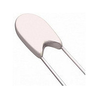
... Vishay Dale NTC Thermistors, Radial Leaded and Coated DESCRIPTION Models M, C, and T are conformally coated, leaded thermistors for standard PC board mounting or assembly in probes. The coating is baked-on phenolic for durability and long-term stability. Models M and C have tinned solid copper leads. Model T has solid nickel wires with Teflon ...

Page 2

... For technical questions, contact: thermistor1@vishay.com Vishay Dale 17 MAXIMUM BODY DIAMETER • 0.125 [3.2] •• 0.110 [2.8] ••• 0.095 [2.4] DISSIPATION CONSTANT 2 mW/° ...

Page 3

... NTC Thermistors, Radial Leaded and Coated Vishay Dale TOLERANCES AVAILABLE FOR TYPE M, C AND T THERMISTORS DESCRIPTION OF THERMISTOR TOLERANCES The many applications of thermistors have mandated the need for two basic tolerance schemes for these products - curve tracking and point match thermistors. An example of the resistance tolerance at various temperatures for the two different ...

Page 4

... TEMPERATURE COMPUTER AIDS FOR THERMISTOR SELECTION A spreadsheet is available for the Vishay thermistor materials that calculates beta, Steinhart-Hart equation constants A, B, and C, the resistance at any temperature based upon the Steinhart constants or beta, the temperature equivalent of the resistance reading, and resistance temperature coefficients. ...

Page 5

... Vishay disclaims any and all liability arising out of the use or application of any product described herein or of any information provided herein to the maximum extent permitted by law. The product specifications do not expand or otherwise modify Vishay’ ...

Related keywords