HVC2512-2MFT18 Welwyn Components, HVC2512-2MFT18 Datasheet - Page 3
HVC2512-2MFT18
Manufacturer Part Number
HVC2512-2MFT18
Description
RESISTOR, 2M 1W 2512 3KV
Manufacturer
Welwyn Components
Series
HVCr
Datasheet
1.HVC2512-10MFT18.pdf
(3 pages)
Specifications of HVC2512-2MFT18
Resistance
2Mohm
Resistance Tolerance
± 1%
Power Rating
1W
Voltage Rating
3kV
Resistor Element Material
Thick Film
Resistor Case Style
2512
No. Of
RoHS Compliant
Temperature Coefficient
± 100ppm/°C


86
Packaging
HVC Resistors are supplied taped and reeled as per IEC 286-3.
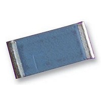
High Voltage
Chip Resistors
HVC Series
HVC resistors are ideally suited for handling by automatic
methods due to their rectangular shape and the small
dimensional tolerances. Electrical connection to a ceramic
substrate or to a printed circuit board can be made by reflow
or wave soldering of wrap-around terminations.
Wrap-around terminations provide good leach properties and
ensure reliable contact. Due to the robust construction, the
HVC can be immersed in the solder bath for 30 seconds at
260°C. This enables the resistor to be mounted on one side
of a printed circuit board and wire-leaded components
applied on the other side.
HVC resistors themselves can operate at a maximum
Ordering Procedure
Example: HVC2512 at 4.7 megohms and 1% tolerance on a reel of 1800 pieces -
Type
Size
Value (use IEC62 code)
Tolerance (use IEC62 code)
© Welwyn Components Limited
Telephone: +44 (0) 1670 822181 · Facsimile: +44 (0) 1670 829465 · Email: info@welwyn-tt.com · Website: www.welwyn-tt.com
Application Notes
D
G
F
Tape and reel dimensions (mm)
1206
2010
2512
(Both sides)
0.5%
1%
2%
Marking
±0.5
Wr
13
13
9
K
J
10%
5%
±0.3
12
12
W
8
HVC
2.5 ± 0.5
±0.1
P1
4
8
8
33 ± 1.0
13 ± 0.5
2512
±0.1
Bedlington, Northumberland NE22 7AA, UK
P0
4
4
4
-
±0.05
P2
2
2
2
4M7
Wr
0.8 ± 0.15
±0.1
1.5
1.5
1.5
D0
F
±0.2
1.5
1.5
D1
1
±0.1
1.75
1.75
1.75
T
1
T 1 8
E
temperature of 155°C (see performance above). For soldered
resistors, the joint temperature should not exceed 110°C. This
condition is met when the stated power levels at 70°C are used.
The PCB layout should avoid tracks running between the HVC
mounting pads, as this would compromise the LEV.
The LEV stated applies to operation at sea-level pressure, in a
non-condensing atmosphere and non-contaminating
environment. Voltage derating should be applied if low
pressure, high humidity or contamination may be encountered.
The termination clearance dimension (B) should be used in
conjunction with the creepage limit applicable to the circuit
application in order to determine the derated LEV.
T
2
T
±0.05
K
3.5
5.5
5.5
0
F
T18
T3
±0.1
1.95
2.79
3.61
A0
A
Tape
0
±0.1
3.55
5.89
6.96
B0
P
D
1
0
±0.1
0.91
1.17
1206 or 2010
2512
1.0
K0
Welwyn Components
±0.05
P
0.28
0.28
2
0.2
T
P
0
D
1
Nom. ±0.15
0.05
0.06
0.06
3000/reel
1800/reel
T1
1.21
1.45
1.3
T2
Issue D · 11.05
Standard
Packing
3000
3000
1800
Qty.
reel
per
Related parts for HVC2512-2MFT18
Image
Part Number
Description
Manufacturer
Datasheet
Request
R

Part Number:
Description:
Thick Film Resistors - SMD 1watt 2M ohm 1%
Manufacturer:
Welwyn Components

Part Number:
Description:
RESISTOR, 10M 1W 2512 3KV
Manufacturer:
Welwyn Components
Datasheet:
Part Number:
Description:
RESISTOR, 3M 1W 2512 3KV
Manufacturer:
Welwyn Components
Datasheet:
Part Number:
Description:
RESISTOR, 100K 1W 2512 3KV
Manufacturer:
Welwyn Components
Datasheet:
Part Number:
Description:
RESISTOR, 1M 1W 2512 3KV
Manufacturer:
Welwyn Components
Datasheet:
Part Number:
Description:
RESISTOR, 20M 1W 2512 3KV
Manufacturer:
Welwyn Components
Datasheet:
Part Number:
Description:
Thick Film Resistors - SMD 1watt 6M ohm 1%
Manufacturer:
Welwyn Components
Part Number:
Description:
Thick Film Resistors - SMD 1watt 220K ohm 1%
Manufacturer:
Welwyn Components
Part Number:
Description:
Thick Film Resistors - SMD 1watt 470K ohm 1%
Manufacturer:
Welwyn Components
Part Number:
Description:
Thick Film Resistors - SMD 1watt 150K ohm 1%
Manufacturer:
Welwyn Components

Part Number:
Description:
Tubular Vitreous Enamelled Wirewound Resistors
Manufacturer:
WELWYN [Welwyn Components Limited]
Datasheet:
Part Number:
Description:
Platinum Temperature Sensor
Manufacturer:
WELWYN [Welwyn Components Limited]
Datasheet:
Part Number:
Description:
High Temperature TaNFilm� Chip Resistors
Manufacturer:
WELWYN [Welwyn Components Limited]
Datasheet:
Part Number:
Description:
High Frequency Chip Resistor Terminators
Manufacturer:
WELWYN [Welwyn Components Limited]
Datasheet:
Part Number:
Description:
Surface Mounted Resistors
Manufacturer:
WELWYN [Welwyn Components Limited]
Datasheet: