ULW4-10RJA1 Welwyn Components, ULW4-10RJA1 Datasheet - Page 4
ULW4-10RJA1
Manufacturer Part Number
ULW4-10RJA1
Description
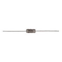
RESISTOR, FUSIBLE, 4W, 10R
Manufacturer
Welwyn Components
Series
ULWr
Datasheet
1.ULW4-10RJA1.pdf
(4 pages)
Specifications of ULW4-10RJA1
Resistance
10ohm
Resistance Tolerance
± 5%
Power Rating
4W
Voltage Rating
500V
Resistor Element Material
Wirewound
Resistor Case Style
Axial Leaded
Temperature Coefficient
± 200ppm/°C
Lead Free Status / RoHS Status
Lead free / RoHS Compliant
Available stocks
Company
Part Number
Manufacturer
Quantity
Price
Company:

Part Number:
ULW4-10RJA1
Manufacturer:
TI
Quantity:
440


UL Recognised Wirewound Resistors
ULW Series
Application Notes
Application Notes
1. If the resistors are to dissipate full rated power, it is recommended that the terminations should not be
soldered closer than 4mm from the body.
2. Due to operating temperature limits imposed by some PCB materials, derating may be necessary. An
estimate of the temperature rise to be expected can be calculated using the thermal impedance figures
given under Electrical Data.
3. For the purposes of UL approval, the following points should be observed:
Packaging
The standard packaging for ULW is taped. The critical dimensions are shown in Figure 1. The component wires will not protrude beyond the outside
edge of the tapes. Taped product is then packed into ammo boxes. Alternative packaging is available by request. Pre-formed resistors are supplied
loose packed in plastic bags or boxes. For SMD leadformed option, see the Z-form datasheet.
Ordering Procedure
Example: ULW2 at 33 ohms and 5% tolerance in ammo pack box of 2500 pieces -
Type
Value (use IEC62 code)
Tolerance (use IEC62 code)
Packing
© Welwyn Components Limited
Telephone: +44 (0)1670 822181 · Facsimile: +44 (0)1670 829465 · Email: info@welwyn-tt.com · Website: www.welwyn-tt.com
A25
A1
J
ULW2
ULW3
ULW4
Type
3.1 To protect against fire under all conditions of overload, a positive clearance of at least
13mm should be provided between the body of the resistor and any combustible materials.
3.2 A positive clearance of 13mm should be provided between the resistor body or terminations
and uninsulated parts of opposite polarity or uninsulated dead metal parts.
3.3 Limited Short Circuit testing should be performed in the complete appliance.
Ammo
5%
Dimensions (mm)
ULW3, ULW4
· Bedlington, Northumberland NE22 7AA, UK
ULW2
52
67
63
b
U L W 2 – 3 3 R J
2500/box
1000/box
A25
10
10
C
5
Standard
Figure 1
6
F
f1
Body location f1 - f2 <1.4mm
Welwyn Components
b
f2
6
C
03. 09
Related parts for ULW4-10RJA1
Image
Part Number
Description
Manufacturer
Datasheet
Request
R

Part Number:
Description:
RESISTORS, POWER PLANAR, 12R 2KW RESISTORS, POWER PLANAR, 12R 2KW
Manufacturer:
Welwyn Components
Datasheet:

Part Number:
Description:
RESISTOR, 6K8, 2W, 10%
Manufacturer:
Welwyn Components
Datasheet:

Part Number:
Description:
RESISTOR, DOUBLE SIDED, 1K5, 2010 CASE
Manufacturer:
Welwyn Components
Datasheet:
Part Number:
Description:
RESISTOR, DOUBLE SIDED, 10R, 2512 CASE
Manufacturer:
Welwyn Components
Datasheet:

Part Number:
Description:
RESISTOR, FUSIBLE, 2W, 10R
Manufacturer:
Welwyn Components
Datasheet:
Part Number:
Description:
RESISTOR, FUSIBLE, 2W, 15R
Manufacturer:
Welwyn Components
Datasheet:
Part Number:
Description:
RESISTOR, FUSIBLE, 2W, 27R
Manufacturer:
Welwyn Components
Datasheet:
Part Number:
Description:
RESISTOR, 1W 5% 180K
Manufacturer:
Welwyn Components
Datasheet:
Part Number:
Description:
RESISTOR, 2W 5% 390K
Manufacturer:
Welwyn Components
Datasheet:

Part Number:
Description:
RESISTOR, 0.4W 1% 22K
Manufacturer:
Welwyn Components
Datasheet:

Part Number:
Description:
Tubular Vitreous Enamelled Wirewound Resistors
Manufacturer:
WELWYN [Welwyn Components Limited]
Datasheet:
Part Number:
Description:
Platinum Temperature Sensor
Manufacturer:
WELWYN [Welwyn Components Limited]
Datasheet:
Part Number:
Description:
High Temperature TaNFilm� Chip Resistors
Manufacturer:
WELWYN [Welwyn Components Limited]
Datasheet:
Part Number:
Description:
High Frequency Chip Resistor Terminators
Manufacturer:
WELWYN [Welwyn Components Limited]
Datasheet:
Part Number:
Description:
Surface Mounted Resistors
Manufacturer:
WELWYN [Welwyn Components Limited]
Datasheet: