ERJP14F4701U Panasonic, ERJP14F4701U Datasheet - Page 4
ERJP14F4701U
Manufacturer Part Number
ERJP14F4701U
Description
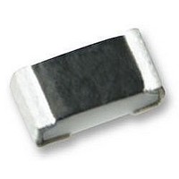
RESISTOR, SURGE, 1210, 1%, 4K7
Manufacturer
Panasonic
Series
ERJPr
Datasheet
1.ERJP03F1000V.pdf
(5 pages)
Specifications of ERJP14F4701U
Resistance
4.7kohm
Resistance Tolerance
± 1%
Power Rating
500mW
Voltage Rating
200V
Resistor Element Material
Thick Film
Resistor Case Style
1210
Temperature Coefficient
± 100ppm/°C
Lead Free Status / RoHS Status
Lead free / RoHS Compliant


■
The following are precautions for individual products. Please also refer to the precautions common to Fixed Resistors
shown on page ER2 of this catalog.
1. Take measures against mechanical stress during and after mounting of Anti-Surge Thick Film Chip Resistors (here af ter
2. If a transient load (heavy load in a short time) like a pulse is expected to be applied, check and evaluate the operations
3. Do not use halogen-based or other high-activity fl ux. Otherwise, the residue may impair the resistors' per for mance
4. When soldering with a soldering iron, never touch the resistors' bodies with the tip of the soldering iron. When using a
5. As the amount of applied solder becomes larger, the mechanical stress applied to the resistors increases, causing
6. Do not apply shock to the resistors or pinch them with a hard tool (e.g. pliers and tweezers). Oth er wise, the re sis tors'
7. Avoid excessive bending of printed circuit boards in order to protect the resistors from abnormal stress.
Design and specifi cations are each subject to change without notice. Ask factory for the current technical specifi cations before purchase and/or use.
Should a safety concern arise regarding this product, please be sure to contact us immediately.
called the resistors) so as not to damage their electrodes and protective coatings.
of the resistors when installed in your products before use.
Never exceed the rated power. Otherwise, the performance and/or reliability of the resistors may be impaired.
and/or reliability.
soldering iron with a high temperature tip, fi nish soldering as quickly as possible (within three seconds at 350 °C max.).
problems such as cracks and faulty characteristics. Avoid applying an excessive amount of solder.
protective coatings and bodies may be chipped, affecting their performance.
Recommended Soldering Conditions
Recommendations and precautions are described below.
● Recommended soldering conditions for refl ow
● Recommended soldering conditions for fl ow
· Refl ow soldering shall be performed a maximum of
· Please contact us for additional information when
· Please measure the temperature of the terminals
Safety Precautions
two times.
used in conditions other than those specifi ed.
and study every kind of solder and printed circuit
board for solderability be fore ac tu al use.
Preheating
Soldering
Preheating
Peak
Time
140 °C to 180 °C
Temperature
245 ± 5 °C
Heating
For soldering
60 s to 120 s
20 s to 30 s
Time
For soldering (Example : Sn/Pb)
For lead-free soldering (Example : Sn/Ag/Cu)
Preheating
Main heating
Peak
Preheating
Main heating
Peak
Anti-Surge Thick Film Chip Resistors
150 °C to 180 °C
Temperature
max. 260 °C
140 °C to 160 °C
150 °C to 180 °C
For lead-free soldering
Above 200 °C
Above 230 °C
Temperature
Temperature
max. 260 °C
235 ± 5 °C
60 s to 120 s
max. 10 s
60 s to 120 s
60 s to 120 s
30 s to 40 s
30 s to 40 s
max. 10 s
Time
max. 10 s
Time
Time
Feb. 2006
Related parts for ERJP14F4701U
Image
Part Number
Description
Manufacturer
Datasheet
Request
R

Part Number:
Description:
Coin Cell Battery with Leads 3V 20mAH 2 PIN HORZ
Manufacturer:
Panasonic
Datasheet:
Part Number:
Description:
Coin Cell Battery with Leads 3V 48mAh 2 pin Vert
Manufacturer:
Panasonic
Part Number:
Description:
Coin Cell Battery 3V 12 X 2.5 mm 48mA
Manufacturer:
Panasonic
Datasheet:
Part Number:
Description:
Coin Cell Battery 3V 48mAh W/TABS
Manufacturer:
Panasonic
Datasheet:
Part Number:
Description:
Color CCD Linear Image Sensor with 1024 Pixels for R and B Colors/2048 Pixels for G Color
Manufacturer:
Panasonic
Datasheet:
Part Number:
Description:
2048-Bit CCD Linear Image Sensor
Manufacturer:
Panasonic
Datasheet:
Part Number:
Description:
2592-Bit CCD Linear Image Sensor
Manufacturer:
Panasonic
Datasheet:
Part Number:
Description:
2048-Bit High-Responsivity CCD Linear Image Sensor with Internal Clock Driver
Manufacturer:
Panasonic
Datasheet:
Part Number:
Description:
2880-Bit High-Responsivity CCD Linear Image Sensor
Manufacturer:
Panasonic
Datasheet:
Part Number:
Description:
Color CCD Linear Image Sensor with 512 Pixels for R and B Colors/1024 Pixels for G Color
Manufacturer:
Panasonic
Datasheet:
Part Number:
Description:
Quad analog switches
Manufacturer:
Panasonic
Datasheet:
Part Number:
Description:
ICs for TV
Manufacturer:
Panasonic
Datasheet:
Part Number:
Description:
IC for Liquid Crystal Color TV
Manufacturer:
Panasonic
Datasheet:
Part Number:
Description:
VCR cylinder direct motor drive circuit
Manufacturer:
Panasonic
Datasheet: