CR0402-J/-000GLF Bourns Inc., CR0402-J/-000GLF Datasheet
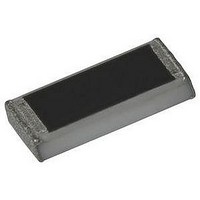
RESISTOR CHIP, JUMPER, ZERO OHM, 1%

CR0402-J/-000GLF

Manufacturer Part Number
CR0402-J/-000GLF
Description
RESISTOR CHIP, JUMPER, ZERO OHM, 1%
Manufacturer
Bourns Inc.
Datasheet

Specifications of CR0402-J/-000GLF

Resistance
0ohm
Resistance Tolerance
± 5%
Power Rating
625mW
Voltage Rating
50V
Resistor Element Material
Thick Film
Resistor Case Style
0402
Temperature Coefficient
+ 500, -250ppm/°C
Material, Element
Metal Element
Package Type
0402
Power, Rating
0.063 W
Termination
SMT
Tolerance
0 Ohms Jumper
Lead Free Status / RoHS Status
Lead free / RoHS Compliant
Power Rating @ 70 °C ................ 1/16 W
Operating Temperature Range
Derated to 0 Load at .................+125 °C
Maximum Working Voltage ..............50 V
Maximum Overload Voltage ..........100 V
Resistance Range
Temperature Coeffi cient
For Standard Values Used in Capacitors,
Inductors, and Resistors,
∆ R/R
*RoHS Directive 2002/95/EC Jan 27 2003 including Annex.
Specifi cations are subject to change without notice.
Customers should verify actual device performance in their specifi c applications.
(%)
Electrical Characteristics
Dimensional Drawings
Characteristic Data
1 %, E-96 and E-24
5 %, E-24
Zero Ohm Jumper ............<0.05 ohms
1 % ................................ ±100 ppm/°C
5 % ................................ ±200 ppm/°C
2.2 ohm to 10 ohms
............................... -55 °C to +125 °C
........................10 ohms to 1 megohm
..................2.2 ohms to 5.6 megohms
............ -200 ppm/°C to +500 ppm/°C
3.0
2.0
1.0
0
Load Life 1000Hr
10
(0.014 ± 0.002)
0.35 ± 0.05
(0.010 ± 0.004)
Resistance Value (Ω)
0.25 ± 0.10
100 1K 10K 100K 1M
(0.008 ± 0.004)
0.20 ± 0.10
click
here.
(0.040 ± 0.004)
(0.010 ± 0.004)
1.00 ± 0.10
0.25 ± 0.10
∆ R/R
Features
CR0402 - Chip Resistor
(%)
DIMENSIONS:
Derating Curve
Small package dimensions
RoHS compliant*
Power rating at 70 °C = 1/16 W
Tight dimensional tolerances
Three layer termination process with
nickel barrier prevents leaching and
provides excellent solderability
3.0
2.0
1.0
(0.020 ± 0.002)
0
0.50 ± 0.05
Moisture Load Life 1000Hr
10
(0.008 ± 0.004)
0.20 ± 0.10
(INCHES)
Resistance Value (Ω)
100 1K 10K 100K 1M
MM
100
80
60
40
20
0
-55
Secondary Electrode (Nickel Plated)
Alumina Substrate
Internal Electrode (Ag-Pd)
(see Part Numbering - may be
0
ordered as solder-plated
Resistor (Ru0
(Jumper chip is
External Electrode
a conductor)
or tin-plated)
∆ R/R
(%)
Suitable for most types of soldering
processes
Standard packaging on paper tape and reel
2
)
-0.5
1.0
0.5
70
0
Short Time Overload
10
Overcoat
Resistance Value (Ω)
100 1K 10K 100K 1M
125

Related parts for CR0402-J/-000GLF

CR0402-J/-000GLF Summary of contents

Page 1

... Small package dimensions ■ RoHS compliant* ■ Power rating at 70 °C = 1/16 W ■ Tight dimensional tolerances ■ Three layer termination process with nickel barrier prevents leaching and provides excellent solderability CR0402 - Chip Resistor Derating Curve 100 -55 0 0.20 ± 0.10 (0.008 ± 0.004) 0.50 ± ...

Page 2

... Part Marking System No Marking on the CR0402 Chip Resistors. <1> 255 °C 220 °C 190 ° seconds 60 - 120 seconds 10 seconds minimum Ramp Up 3 ° ...

Page 3

... CR0402 - Chip Resistor How to Order Model (CR = Chip Resistor) Size • 0402 Resistance Tolerance F = ±1 % .............Used with “X” TCR code only for values from 10 ohms through 1 megohm ±5 % ............... Used with “W” TCR code for values from 10 ohms through 5.6 megohms. Used with “/” TCR code for zero ohm (jumper) and for values from 1 ohm through 9.1 ohms. TCR (ppm/° ...

Related keywords