TC122-JR-07470RL Yageo, TC122-JR-07470RL Datasheet - Page 4
TC122-JR-07470RL
Manufacturer Part Number
TC122-JR-07470RL
Description
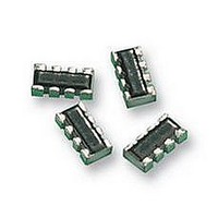
RESISTOR ARRAY, ARC321, 470R
Manufacturer
Yageo
Series
TC122r
Datasheet
1.TC122-JR-07100KL.pdf
(8 pages)
Specifications of TC122-JR-07470RL
Resistance
470ohm
Resistance Tolerance
± 5%
Power Rating
63mW
Voltage Rating
50V
Temperature Coefficient
± 200ppm/°C
No. Of Elements
2
Resistor Case Style
SMD
Svhc
No SVHC
Lead Free Status / RoHS Status
Lead free / RoHS Compliant


MARKING
For further marking information, please see special data sheet “Chip resistors marking”.
CONSTRUCTION
The resistor is constructed on top
of a high-grade ceramic body.
Internal metal electrodes are added
on each end to make the contacts to
the thick film resistive element. The
composition of the resistive element
is a noble metal imbedded into a
glass and covered by a second glass
to prevent environment influences.
The resistor is laser trimmed to the
rated resistance value. The resistor
is covered with a protective epoxy
coat, finally the two external
terminations (matte tin on Ni-
barrier) are added. See fig.3
DIMENSIONS
SCHEMATIC
YC122
TYPE
B (mm)
H (mm)
P (mm)
L (mm)
T (mm)
W
W
Sep 16, 2008 V.2
For dimension see Fig. 4 and Table 1
1
2
Fig. 1
Table 1
Fig. 5 Equivalent circuit diagram
(mm)
(mm)
Chip Resistor Surface Mount
ynsc008
0.21 +0.10/–0.05
0.20 ±0.10
0.67 ±0.05
1.00 ±0.10
0.30 ±0.10
0.25 ±0.10
1.00 ±0.10
YC122
TC122
O
O
U
Fig. 2
U
Fig. 3 Chip resistor outlines
T
T
0.25 ±0.15
0.30 ±0.05
0.50 ±0.05
1.00 ±0.10
0.30 ±0.10
0.25 ±0.15
1.00 ±0.10
L
L
I
I
N
N
TC122
E
E
YC/TC
S
S
ynsc060
SERIES
YC122
For dimension see Table 1
YC122
Fig. 4 YC/TC122 series chip resistors dimension
R1 = R2
B
122 (RoHS Compliant)
4
1
R1
P
L
R2
3
2
H
No marking
TC122
TC122
B
overcoat
resistive layer
inner electrode
termination
ceramic substrate
R1 = R2
H
P
L
4
1
R1
Product specification
3
2
R2
YNSC069
www.yageo.com
T
YNSC067
YNSC068
W
1
W
2
4
8
Related parts for TC122-JR-07470RL
Image
Part Number
Description
Manufacturer
Datasheet
Request
R

Part Number:
Description:
RESISTOR ARRAY, ARC321, 100K
Manufacturer:
Yageo
Datasheet:
Part Number:
Description:
RESISTOR ARRAY, ARC321, 100R
Manufacturer:
Yageo
Datasheet:
Part Number:
Description:
RESISTOR ARRAY, ARC321, 10K
Manufacturer:
Yageo
Datasheet:
Part Number:
Description:
RESISTOR ARRAY, ARC321, 1K
Manufacturer:
Yageo
Datasheet:
Part Number:
Description:
RESISTOR ARRAY, ARC321, 220K
Manufacturer:
Yageo
Datasheet:
Part Number:
Description:
RESISTOR ARRAY, ARC321, 220R
Manufacturer:
Yageo
Datasheet:
Part Number:
Description:
RESISTOR ARRAY, ARC321, 22K
Manufacturer:
Yageo
Datasheet:
Part Number:
Description:
RESISTOR ARRAY, ARC321, 22R
Manufacturer:
Yageo
Datasheet:
Part Number:
Description:
RESISTOR ARRAY, ARC321, 2K2
Manufacturer:
Yageo
Datasheet:
Part Number:
Description:
RESISTOR ARRAY, ARC321, 470K
Manufacturer:
Yageo
Datasheet:


Part Number:
Description:
YAGEO 22pF ±5% 50V NPO
Manufacturer:
Yageo
Datasheet:
