STRS30102K ALPS, STRS30102K Datasheet - Page 6
STRS30102K
Manufacturer Part Number
STRS30102K
Description
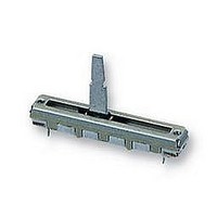
POTENTIOMETER, SLIDE 50K POTENTIOMETER, SLIDE 50K
Manufacturer
ALPS
Series
RSr
Datasheet
1.STRS30102K.pdf
(7 pages)
Specifications of STRS30102K
Variable Sliding
RESISTANCE, TRACK
Power Rating
0.1W
Travel
30MM
Case Style
PCB MOUNT
Pitch, Hole
41MM
Tolerance, +
20%
Tolerance, -
20%
Rohs Compliant
YES
Track Resistance
50kohm
Track Taper
Linear
Resistance Tolerance
± 20%
Voltage Rating
200VAC


B
FOLLOW THE NEXT CQWDITIOHS FOR SOLDERING
1.
2. Board In Use
3. In the Case of Dip Soldering
4. in the Case of Manual Soldering
(1) State of potentiometer
(3) Height of Flux face
(4) Preheat Condition
(2) Specific Gravity of Flux
(5) Soldering Condition
Solder
63 % Sn solder specified In JZS Z3282.
Double-faces through-hole board or
Single-face copper laid laminate board*
Plate thickness (t) - 1.6 mm
Solder temperature
Soldering period
Tine of soldering
A level of the upper face of flux for reaching the position
Position a lever in the vicinity of center.
0.83±0.0l (foaming type)
at a half of the plate thickness of printed board. ( Fig.l)
Further, no flow of flux invading on the surface of printed
board on the side of installing potentiometer is allowed.
100*C MAX..within 1 minute
( Temperature on the side of installing printed board is
Solder temperature; 26O'C MAX.
Soldering period
Tine of soldering ; only one time is permitted
designated.
)
POTENTIOMETER
; within 5 seconds
; 300#C MAX.
; within 3 seconds
; only one time is permitted
86S66
{ Fig. 1 )
5. Matters to Be Noted
(1) Do not add any stress on terminals In the case of soldering.
(2) Avoid use of double-faces through-hole board as much as
(3) Use caution to soldering process so as to prevent solder
(4) In the case of lead wiring, solder it so that a gap of 1 mm
(5) The grade of Influence of soldering exerted on the
For instance, forced movement of potentiometer with
between resistant board and terminals.
terminals being heated may probably deteriorate the electric
features due to generation of looseness In connection
possible. If it is necessary to use It. Do not apply through
-hole plating to a hole in which a potentiometer is Inserted,
and Install a land to which terminals are soldered only on a
face opposite to the face on the side of installing
potentiometer.
from rlaing up to the surface of printed board on the aide
of Installing potentiometer,because defective contact may
take place In terminal connecting part due to soldering heat
( Fig. 2 )
or more nay be reserved between the potentiometer body and
soldering part. < Fig* 3 )
potentiometer depends upon the site of a printed board,
installing position of the potentiometer, and the size of a
solder bath etc. Therefore, make sure, in advance, of no
abnomal state under the conditions of soldering to be
carried our at present.
MODNTIHG SIDE
TERMINAL
t Fig. 2 )
ill
POTENTIOMETER
( Fig. 3 )
,
'
Related parts for STRS30102K
Image
Part Number
Description
Manufacturer
Datasheet
Request
R
