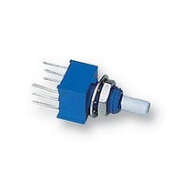
3310H-1-102L Bourns Inc., 3310H-1-102L Datasheet - Page 28

3310H-1-102L
Manufacturer Part Number
3310H-1-102L
Description
POTENTIOMETER, 1K
Manufacturer
Bourns Inc.
Series
3310Hr
Datasheet
1.3310H-1-102L.pdf
(54 pages)
Specifications of 3310H-1-102L
Track Resistance
1kohm
Track Taper
Linear
No. Of Turns
1
Resistance Tolerance
± 20%
Voltage Rating
200V
Power Rating
250mW
No. Of Gangs
2
Svhc
No SVHC (15-Dec-2010)
Resistor Element
RoHS Compliant
Potentiometer Mounting
PCB
Rohs Compliant
Yes
230
Standard resistance Range (A & H Tapers)..........................................................................................................................................100 ohm to 5 megohms
Resistance Tolerance ........................................................................................................................................................................................(A Taper) ±10%
Independent Linearity.........................................................................................................................................................................................................±5%
Absolute Minimum Resistance......................................................................................................................................................................2 ohms maximum
Continuity .........................................................................................................................................................................Maintained for full mechanical angle
Effective Electrical Angle............................................................................................................................................................................................260° ±10°
Contact Resistance Variation................................................................................................................................................................±3% of total resistance
Theoretical Resolution ...................................................................................................................................................................................Essentially infinite
Dielectric Withstanding Voltage ......................................................................................................................................................MIL-STD-202, Method 301
Insulation Resistance (500 VDC) ......................................................................................................................................................1,000 megohms minimum
Power Rating (Voltage Limited by Power Dissipation or 350 VAC, Whichever is Less)
Operating Temperature .....................................................................................................................................................................................-1°C to +125°C
Storage Temperature Range ...........................................................................................................................................................................-65°C to +125°C
Temperature Coefficient Over Temperature Range ..............................................................................................................................................±150 ppm/°C
Vibration .............................................................................................................................................................................................................................20G
Shock ..................................................................................................................................................................................................................................50G
Load Life .................................................................................................................................................................................................................1,000 hours
Rotational Life (C & N Bushing) (No Load)...........................................................................................................................................................50,000 cycles
Moisture Resistance ..................................................................................................................................................MIL-STD-202, Method 106, Condition B
Salt Spray...................................................................................................................................................................MIL-STD-202, Method 101, Condition A
Shaft Torque .........................................................................................5 oz.-in. (3.53 Ncm) maximum
Shaft Locking Torque with Locking Bushings ...................................................20 oz.-in. (14.12 Ncm)
Mechanical Angle ...................................................................................................................295° ±3°
Weight ...................................................................................................................25 grams maximum
Terminals..............................................................................................Printed circuit pins or J-Hooks
Markings........Mfr’s. trademark, wiring diagram, date code, resistance, manufacturer’s part number
Stop Strength............................................................................................................3 in-lb. maximum
1
AT ROOM AMBIENT: +25°C NOMINAL AND 50% RELATIVE HUMIDITY NOMINAL, EXCEPT AS NOTED.
Initial Electrical Characteristics
Environmental Characteristics
Mechanical Characteristics
3862E/T
(.475 .030)
Sea Level ...................................................................................................................................................................................................750 VAC minimum
70,000 Feet................................................................................................................................................................................................350 VAC minimum
+70°C ............................................................................................................................................................................................................................1 watt
+125°C ..........................................................................................................................................................................................................................0 watt
Total Resistance Shift .....................................................................................................................................................................................±2% maximum
Voltage Ratio Shift ..........................................................................................................................................................................................±6% maximum
Total Resistance Shift .....................................................................................................................................................................................±3% maximum
Total Resistance Shift .....................................................................................................................................................................................±5% maximum
Total Resistance Shift .....................................................................................................................................................................................±2% maximum
Insulation Resistance (500 VDC) ......................................................................................................................................................100 megohms minimum
12.07 .76
(1/4)
6.25
DIA.
-32 UNEF - 2A
DIMENSIONS ARE:
POSITION OF SLOTS VARIABLE
L =
(.500 .016)
(.453 .016)
11.51 .41
12.7 .41
(.375)
9.53
FOR "T" BUSHING,
(INCHES)
METRIC
(.500)
12.7
15.88
(5/8)
(.035 .010)
.89 .25
2 PLCS.
L
FOR "E" BUSHING
1
STD.
1
1
(.125 .001)
3.18 .03
(.031 .010)
45
.79 .25
(.03)
1.79
DIA.
5 X
Features
3862 - 1/2” Diameter Single-Turn Panel Control
(.016)
(.475 .030)
12.07 .76
.41
Small diameter
Wide resistance range
Good resolution
Linear tapers
DIA.
(1/4)
6.25
(.500 .016)
(.453 .016)
11.51 .41
12.7 .41
3862C/N
-32 UNEF - 2A
FROM BUSHING FOR SHAFTS UNDER
OPTIONAL FLAT
L =
(.250)
6.35
FOR "C" BUSHING,
(.250)
6.35
L
9.53, 22.23
(3/8, 7/8)
(.035 .010)
LONG OR
.89 .25
2 PLCS.
(.380)
9.65
STD.
(.13) 16.88
(.094)
3.3
2.38
FOR "N" BUSHING
(5/8)
(.125 .001)
3.18 .03
(.031 .010)
.79 .25
PCB LAYOUT
(.200)
5.08
45
(.031)
DIA.
.79
5 X
Specifications are subject to change without notice.
(.120)
3.04
(.016)
.41
(.100)
2.54
TYP.
(.200)
5.08
2 PLCS.
(.245)
6.22
C OF LUG
Shaft End Detail
3862
L
PANEL LAYOUT
45
45
(.245)
6.22
15
(.265)
6.73
DIA.
32-1/2
FLAT ORIENTATION
@ CCW END
SLOTS ARE
NOT ORIENTED
(H Taper) ±5%
(.091)
2.31
(.096 + .005/ - .000)
DIA. 2 PLCS.
2.44 .13
2 PLCS.
10
(.245)
6.22
2 PLCS.
(.010)
.25


